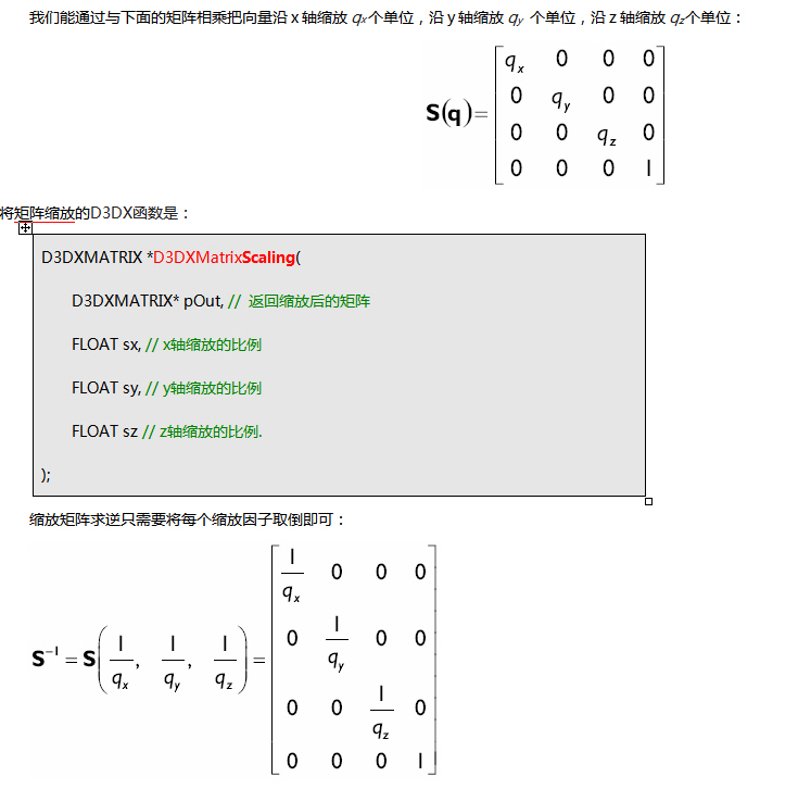
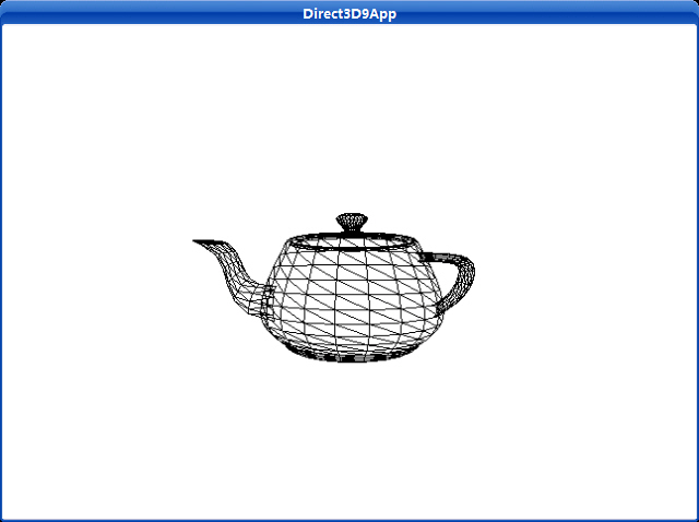
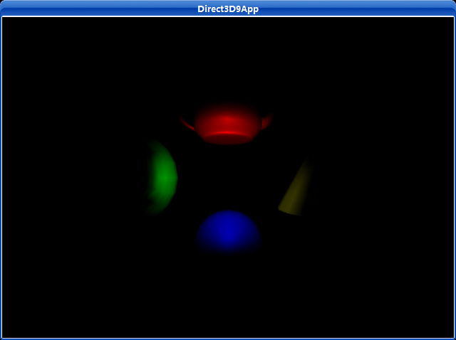
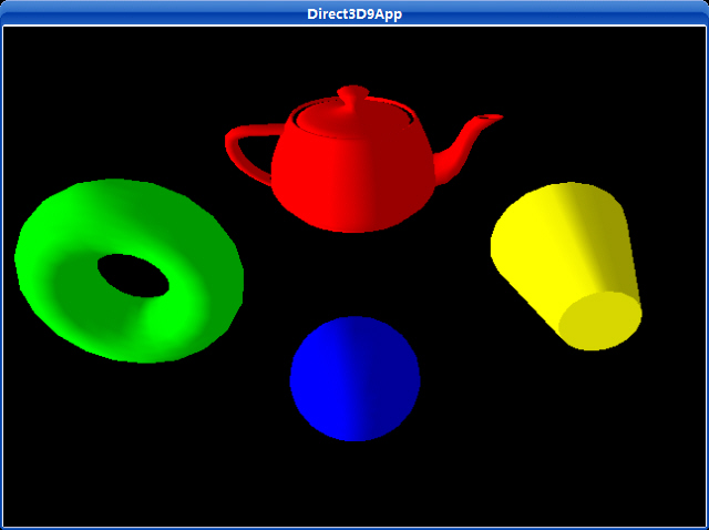
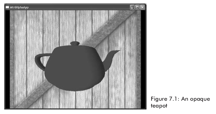
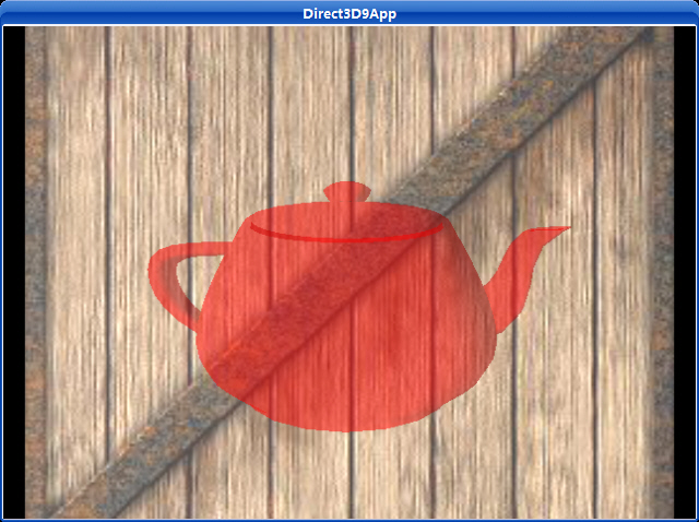
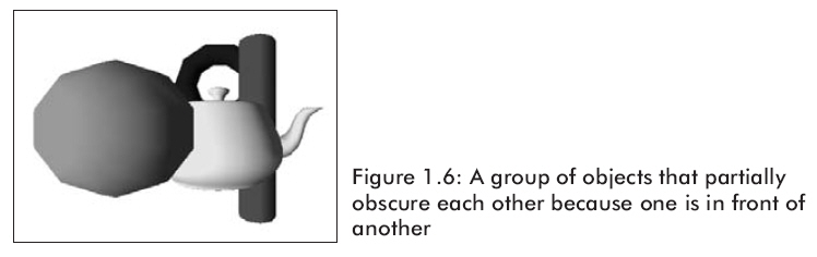
这个程序使用D3DXCreateTeapot函数创建并用DrawSubset函数渲染一个纺纱茶壶。

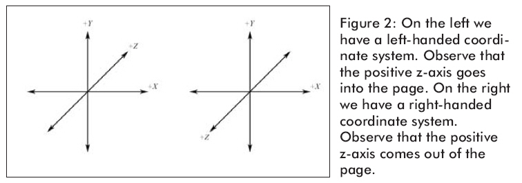
Uses a left-handed coordinate system to create a mesh containing a teapot.

HRESULT D3DXCreateTeapot(
LPDIRECT3DDEVICE9 pDevice,
LPD3DXMESH * ppMesh,
LPD3DXBUFFER * ppAdjacency
);
Parameters
pDevice
[in] Pointer to an IDirect3DDevice9 interface, representing the device associated with the created teapot mesh.
ppMesh
[out] Address of a pointer to the output shape, an ID3DXMesh interface.
ppAdjacency
[out] Address of a pointer to an ID3DXBuffer interface. When the method returns, this parameter is filled with an array of three DWORDs per face that specify the three neighbors for each face in the mesh. NULL can be specified.
Return Values

If the function succeeds, the return value is D3D_OK. If the function fails, the return value can be one of the following: D3DERR_INVALIDCALL, D3DXERR_INVALIDDATA, E_OUTOFMEMORY.

Remarks

This function creates a mesh with the D3DXMESH_MANAGED creation option and D3DFVF_XYZ | D3DFVF_NORMAL flexible vertex format (FVF).

Draws a subset of a mesh.

HRESULT DrawSubset(
DWORD AttribId
);
Parameters
AttribId
[in] DWORD that specifies which subset of the mesh to draw. This value is used to differentiate faces in a mesh as belonging to one or more attribute groups.
Return Values

If the method succeeds, the return value is D3D_OK. If the method fails, the return value can be D3DERR_INVALIDCALL.

Remarks

The subset that is specified by AttribId will be rendered by the IDirect3DDevice9::DrawIndexedPrimitive method, using the D3DPT_TRIANGLELIST primitive type, so an index buffer must be properly initialized.

An attribute table is used to identify areas of the mesh that need to be drawn with different textures, render states, materials, and so on. In addition, the application can use the attribute table to hide portions of a mesh by not drawing a given attribute identifier (AttribId) when drawing the frame.
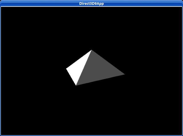
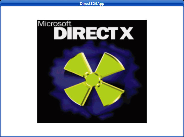
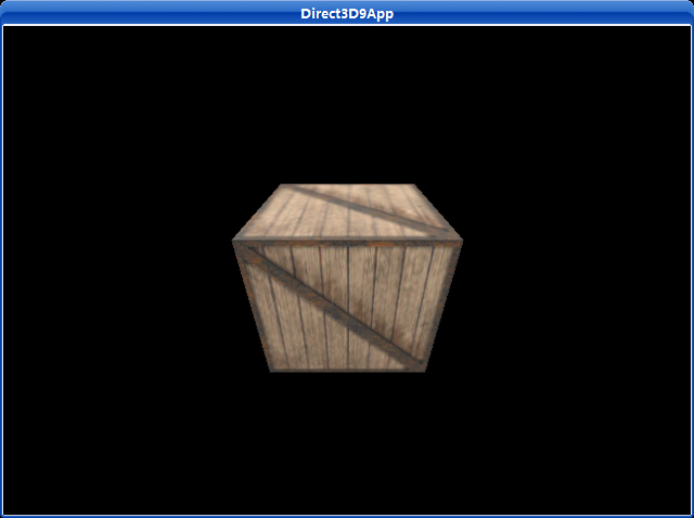
截图:

源程序:

/**************************************************************************************
  Renders a teapot in wireframe mode.  Shows how to create a teapot using the
  D3DXCreateTeapot function and how to render the teapot using the ID3DXMesh::DrawSubset
  method.
**************************************************************************************/
#include "d3dUtility.h"
#pragma warning(disable : 4100)
const int WIDTH  = 640;
const int HEIGHT = 480;
IDirect3DDevice9*    g_d3d_device = NULL;
// mesh interface that will store the teapot data and contains method to render the teapot data
ID3DXMesh* g_teapot_mesh = NULL;
////////////////////////////////////////////////////////////////////////////////////////////////////
bool setup()
{   
// create the teapot geometry
    D3DXCreateTeapot(g_d3d_device, &g_teapot_mesh, NULL);
// position and aim the camera
    D3DXVECTOR3 position(0.0f, 0.0f, -3.0f);
    D3DXVECTOR3 target(0.0f, 0.0f, 0.0f);
    D3DXVECTOR3 up(0.0f, 1.0f, 0.0f);
    D3DXMATRIX view_matrix;
    D3DXMatrixLookAtLH(&view_matrix, &position, &target, &up);
    g_d3d_device->SetTransform(D3DTS_VIEW, &view_matrix);
// set the projection matrix
    D3DXMATRIX proj;
    D3DXMatrixPerspectiveFovLH(&proj, D3DX_PI * 0.5f, (float)WIDTH/HEIGHT, 1.0f, 1000.0f);
    g_d3d_device->SetTransform(D3DTS_PROJECTION, &proj);
// set wireframe mode render state
    g_d3d_device->SetRenderState(D3DRS_FILLMODE, D3DFILL_WIREFRAME);
return true;
}
void cleanup()
{
    safe_release<ID3DXMesh*>(g_teapot_mesh);
}
bool display(float time_delta)
{
// spin the teapot
    D3DXMATRIX ry;
static float y = 0.0f;
    D3DXMatrixRotationY(&ry, y);
// increment y-rotation angle each frame
    y += time_delta;
// reset angle to zero when angle reaches 2*PI
if(y >= 6.28f)
        y = 0.0f;
    g_d3d_device->SetTransform(D3DTS_WORLD, &ry);
// draw the scene
    g_d3d_device->Clear(0, NULL, D3DCLEAR_TARGET | D3DCLEAR_ZBUFFER, 0xffffffff, 1.0f, 0);
    g_d3d_device->BeginScene();
// draw teapot using DrawSubset method with 0 as the argument
    g_teapot_mesh->DrawSubset(0);
    g_d3d_device->EndScene();
    g_d3d_device->Present(NULL, NULL, NULL, NULL);
return true;
}
LRESULT CALLBACK wnd_proc(HWND hwnd, UINT msg, WPARAM word_param, LPARAM long_param)
{
switch(msg)
    {
case WM_DESTROY:
        PostQuitMessage(0);
break;
case WM_KEYDOWN:
if(word_param == VK_ESCAPE)
            DestroyWindow(hwnd);
break;
    }
return DefWindowProc(hwnd, msg, word_param, long_param);
}
int WINAPI WinMain(HINSTANCE inst, HINSTANCE, PSTR cmd_line, int cmd_show)
{
if(! init_d3d(inst, WIDTH, HEIGHT, true, D3DDEVTYPE_HAL, &g_d3d_device))
    {
        MessageBox(NULL, "init_d3d() - failed.", 0, MB_OK);
return 0;
    }
if(! setup())
    {
        MessageBox(NULL, "Steup() - failed.", 0, MB_OK);
return 0;
    }
    enter_msg_loop(display);
    cleanup();
    g_d3d_device->Release();
return 0;
}

下载茶壶源程序

3.1顶点/索引缓存

       顶点和索引缓存有相似的接口并且共享相似的方法;因此我们把它们合在一起讲解。一个顶点缓存是一块连续的存储了顶点数据的内存。同样的,一个索引缓存是一块连续的存储了索引数据的内存。我们使用顶点和索引缓存保存我们的数据是因为它们能被放置在显存中。渲染显存中的数据要比渲染系统内存中的数据快的多。

       在代码中,一个顶点缓存是通过IDirect3DVertexBuffer9接口来定义的。类似的,一个索引缓存是通过IDirect3DIndexBuffer9接口来定义。

3.1.1创建一个顶点和索引缓存

我们能使用下面两个方法创建一个顶点缓存和索引缓存:

HRESULT IDirect3DDevice9::CreateVertexBuffer(

       UINT Length,

       DWORD Usage,

       DWORD FVF,

       D3DPOOL Pool

       IDirect3DVertexBuffer9** ppVertexBuffer,

       HANDLE* pSharedHandle

);

HRESULT IDirect3DDevice9::CreateIndexBuffer(

       UINT Length,

       DWORD Usage,

       D3DFORMAT Format,

       D3DPOOL Pool,

       IDirect3DIndexBuffer9** ppIndexBuffer,

       HANDLE* pSharedHandle

);

这两个方法大部分参数是相同的,因此我们一起介绍它们。

Length —— 分配给缓存的字节大小。假如想得到一个能存储8个顶点的顶点缓存,那么我们就要在顶点结构中设置这个参数为 8 * sizeof ( Vertex ) 。

Usage —— 指定关于怎样使用缓存的额外信息。这个值可以是0,没有标记,或者是下面标记的一个或多个的组合:

         D3DUSAGE_DYNAMIC——设置这个参数可以使缓存是动态的。

         D3DUSAGE_POINTS——这个参数指定缓存存储原始点。这个参数仅仅用在顶点缓冲中。

         D3DUSAGE_SOFTWAREPROCESSING——使用软件顶点处理

         D3DUSAGE_WRITEONLY——指定应用程序只能写缓存。它允许驱动程序分配最适合的内存地址作为写缓存。注意如果从创建好的这种缓存中读数据,将会返回错误信息。

FVF —— 存储在缓存中的顶点格式

Pool —— 缓存放置在哪一个内存池中

ppVertexBuffer ——返回创建好的顶点缓存的指针。

pSharedHandle ——没有使用;设置为0。

Format ——指定索引的大小;使用D3DFMT_INDEX16设置16位索引,使用D3DFMT_INDEX32设置32位索引。注意并非所有设备都支持32位索引;请检查设备能力。

ppIndexBuffer ——返回创建好的索引缓存的指针。

注意:不使用D3DUSAGE_DYNAMIC参数创建的缓存被叫做静态缓存。静态缓存通常被放置在显存中,在其中的数据能被很有效的处理。然而,对于静态缓存,从中读取和写入数据是很慢的,因为访问显存是很慢的。因为这个原因我们用静态缓存存储静态数据(不需要被经常改变的数据)。地形和建筑物是很好的候选例子,因为在应用程序中他们通常不需要被改变。静态缓存应该在应用程序初始化的时候就被填充好,而不是在运行时才做。

注意:使用D3DUSAGE_DYNAMIC参数创建的缓存被叫做动态缓存。动态缓存通常被放在AGP内存中,这种内存中的数据能被很快的更新。处理动态缓存中的数据不会比处理静态缓存中的数据快,因为这些数据必须在渲染前被转移到显存中,动态缓存的好处是它们能够被稍微快点地被更新(比CPU写快)。因此,假如你需要经常更新缓存中的数据,那么你就应该使用动态缓存。粒子系统是很好的一个应用,因为它们是动态的,并且他们通常每一帧都会被更新。

注意:在程序中读取显存和AGP内存都是非常慢的。因此,假如你在运行时需要读取你的几何物体,最好的方案是指定一块系统内存,往其中拷贝并且读取数据。

下边是创建一个静态顶点缓存的例子,该缓存能存储8个顶点。

IDirect3DVertexBuffer9* vb;

device->CreateVertexBuffer( 8 * sizeof( Vertex ),    0,    D3DFVF_XYZ,  D3DPOOL_MANAGED, &vb, 0);

3.1.2 访问缓冲内存

为了访问一个顶点/索引缓存,我们需要得到一个指针。我们通过一个指针获得缓存数据必须使用Lock方法。当我们访问完缓存后必须对它解锁。一旦有一个指向内存的指针,我们就能对它进行读写。

HRESULT IDirect3DVertexBuffer9::Lock(

       UINT OffsetToLock,

       UINT SizeToLock,

       BYTE** ppbData,

       DWORD Flags

);

HRESULT IDirect3DIndexBuffer9::Lock(

       UINT OffsetToLock,

       UINT SizeToLock,

       BYTE** ppbData,

       DWORD Flags

);

这两个方法的参数都是完全相同的。

OffsetToLock —— 偏移量,以字节为单位,从缓存开始位置到锁定开始位置的距离。如图3.1。

SizeToLock —— 锁定的字节数。

ppbData —— 一个指向锁定内存开始位置的指针。

Flags —— 标记描述怎样锁定内存。它可能是0或者是下面参数中的1个或多个的组合:

       D3DLOCK_DISCARD——这个参数仅仅会在动态缓存时被使用。它指示硬件丢弃缓存并返回一个指向新分配的缓存的指针。这是很有用,因为当我们存取一个新分配的缓存时它允许硬件继续从丢弃的缓存渲染。这防止了硬件延迟。

       D3DLOCK_NOOVERWRITE——这个参数仅仅会在动态缓存时被使用。它声明你将向缓存中添加数据。即你不能向已经渲染的内存中写数据。这是有好处的因为他允许你在添加新数据到缓存的同时让硬件继续渲染。

       D3DLOCK_READONLY——这个参数声明你锁定的缓存只能从中读取数据而不能写数据。这允许一些内在的优化。

       用参数D3DLOCK_DISCARD和D3DLOCK_NOOVERWRITE表明缓存的一部分被锁定之后能继续被使用。假如硬件配置允许这些标记被使用,则在对缓存进行锁定时,其他的显示操作就不会中断。

       下边的例子展示了通常怎样使用Lock方法。注意当我们使用完以后要调用Unlock方法。

Vertex* vertices;

_vb->Lock(0, 0, (void**)&vertices, 0); // 锁定整个缓存

vertices[0] = Vertex(-1.0f, 0.0f, 2.0f); // 向缓存里写顶点

vertices[1] = Vertex( 0.0f, 1.0f, 2.0f);

vertices[2] = Vertex( 1.0f, 0.0f, 2.0f);

_vb->Unlock(); // 当你访问完缓存时,解锁缓存

3.1.3 找回顶点和索引缓存信息

有时我们需要得到顶点/索引缓存信息。下面的例子示范了用于获得这些信息的方法:

D3DVERTEXBUFFER_DESC vbDescription;

_vertexBuffer->GetDesc(&vbDescription); // 取得顶点缓存信息

D3DINDEXBUFFER_DESC ibDescription;

_indexBuffer->GetDesc(&ibDescription); //取得索引缓存信息

D3DVERTEXBUFFER_DESC和D3DINDEXBUFFER_DESC结构的定义如下:

Describes a vertex buffer.

typedef struct D3DVERTEXBUFFER_DESC {
D3DFORMAT Format;
D3DRESOURCETYPE Type;
DWORD Usage;
D3DPOOL Pool;
UINT Size;
DWORD FVF;
} D3DVERTEXBUFFER_DESC, *LPD3DVERTEXBUFFER_DESC;
Members
Format
Member of the D3DFORMAT enumerated type, describing the surface format of the vertex buffer data.
Type
Member of the D3DRESOURCETYPE enumerated type, identifying this resource as a vertex buffer.
Usage
Combination of one or more D3DUSAGE flags.
Pool
Member of the D3DPOOL enumerated type, specifying the class of memory allocated for this vertex buffer.
Size
Size of the vertex buffer, in bytes.
FVF
Combination of D3DFVF that describes the vertex format of the vertices in this buffer.

Defines resource types.

typedef enum D3DRESOURCETYPE
{
D3DRTYPE_SURFACE = 1,
D3DRTYPE_VOLUME = 2,
D3DRTYPE_TEXTURE = 3,
D3DRTYPE_VOLUMETEXTURE = 4,
D3DRTYPE_CubeTexture = 5,
D3DRTYPE_VERTEXBUFFER = 6,
D3DRTYPE_INDEXBUFFER = 7,
D3DRTYPE_FORCE_DWORD = 0x7fffffff,
} D3DRESOURCETYPE, *LPD3DRESOURCETYPE;
Constants
D3DRTYPE_SURFACE
Surface resource.
D3DRTYPE_VOLUME
Volume resource.
D3DRTYPE_TEXTURE
Texture resource.
D3DRTYPE_VOLUMETEXTURE
Volume texture resource.
D3DRTYPE_CubeTexture
Cube texture resource.
D3DRTYPE_VERTEXBUFFER
Vertex buffer resource.
D3DRTYPE_INDEXBUFFER
Index buffer resource.
D3DRTYPE_FORCE_DWORD
Forces this enumeration to compile to 32 bits in size. Without this value, some compilers would allow this enumeration to compile to a size other than 32 bits. This value is not used.

Describes an index buffer.

typedef struct D3DINDEXBUFFER_DESC {
D3DFORMAT Format;
D3DRESOURCETYPE Type;
DWORD Usage;
D3DPOOL Pool;
UINT Size;
} D3DINDEXBUFFER_DESC, *LPD3DINDEXBUFFER_DESC;
Members
Format
Member of the D3DFORMAT enumerated type, describing the surface format of the index buffer data.
Type
Member of the D3DRESOURCETYPE enumerated type, identifying this resource as an index buffer.
Usage
Combination of one or more of the following flags, specifying the usage for this resource.
D3DUSAGE_DONOTCLIP
Set to indicate that the index buffer content will never require clipping.
D3DUSAGE_DYNAMIC
Set to indicate that the index buffer requires dynamic memory use. This is useful for drivers because it enables them to decide where to place the buffer. In general, static index buffers are placed in video memory and dynamic index buffers are placed in AGP memory. Note that there is no separate static usage; if you do not specify D3DUSAGE_DYNAMIC the index buffer is made static. D3DUSAGE_DYNAMIC is strictly enforced through the D3DLOCK_DISCARD and D3DLOCK_NOOVERWRITE locking flags. As a result, D3DLOCK_DISCARD and D3DLOCK_NOOVERWRITE are only valid on index buffers created with D3DUSAGE_DYNAMIC; they are not valid flags on static vertex buffers.

For more information about using dynamic index buffers, see Using Dynamic Vertex and Index Buffers.

Note that D3DUSAGE_DYNAMIC cannot be specified on managed index buffers. For more information, see Managing Resources (Direct3D 9).

D3DUSAGE_RTPATCHES
Set to indicate when the index buffer is to be used for drawing high-order primitives.
D3DUSAGE_NPATCHES
Set to indicate when the index buffer is to be used for drawing N patches.
D3DUSAGE_POINTS
Set to indicate when the index buffer is to be used for drawing point sprites or indexed point lists.
D3DUSAGE_SOFTWAREPROCESSING
Set to indicate that the buffer is to be used with software processing.
D3DUSAGE_WRITEONLY
Informs the system that the application writes only to the index buffer. Using this flag enables the driver to choose the best memory location for efficient write operations and rendering. Attempts to read from an index buffer that is created with this capability can result in degraded performance.
Pool
Member of the D3DPOOL enumerated type, specifying the class of memory allocated for this index buffer.
Size
Size of the index buffer, in bytes.

点光源示例,截图:

源代码:

/**************************************************************************************
  Demonstrates using a point light with D3DX objects. 
  You can orbit the scene using the left and right arrow keys. 
  In addition you can elevate the camera with the up and down arrow keys. 
**************************************************************************************/
#include "d3dUtility.h"
#pragma warning(disable : 4100)
#define MESH_TEAPOT        0
#define MESH_SPHERE        1
#define MESH_TORUS        2
#define MESH_CYLINDER    3
#define NUM_MESH        4
const int WIDTH  = 640;
const int HEIGHT = 480;
IDirect3DDevice9*        g_d3d_device  = NULL;
ID3DXMesh*                g_object_meshes[NUM_MESH];
D3DXMATRIX                g_world_matrices[NUM_MESH];
D3DMATERIAL9            g_materials[NUM_MESH];
////////////////////////////////////////////////////////////////////////////////////////////////////
bool setup()
{   
// create objects
    D3DXCreateTeapot(g_d3d_device, &g_object_meshes[MESH_TEAPOT], NULL);
    D3DXCreateSphere(g_d3d_device, 1.0f, 20, 20, &g_object_meshes[MESH_SPHERE], NULL);
    D3DXCreateTorus(g_d3d_device, 0.5f, 1.0f, 20, 20, &g_object_meshes[MESH_TORUS], NULL);
    D3DXCreateCylinder(g_d3d_device, 0.5f, 1.0f, 2.0f, 20, 20, &g_object_meshes[MESH_CYLINDER], NULL);
// build world matrices - position the objects in world space
    D3DXMatrixTranslation(&g_world_matrices[MESH_TEAPOT],     0.0f,  2.0f, 0.0f);
    D3DXMatrixTranslation(&g_world_matrices[MESH_SPHERE],     0.0f, -2.0f, 0.0f);
    D3DXMatrixTranslation(&g_world_matrices[MESH_TORUS],    -3.0f,  0.0f, 0.0f);
    D3DXMatrixTranslation(&g_world_matrices[MESH_CYLINDER],     3.0f,  0.0f, 0.0f);
// setup the object's materials
    g_materials[MESH_TEAPOT]   = RED_MATERIAL;
    g_materials[MESH_SPHERE]   = BLUE_MATERIAL;
    g_materials[MESH_TORUS]    = GREEN_MATERIAL;
    g_materials[MESH_CYLINDER] = YELLOW_MATERIAL;
// setup a directional light, note that the point light is positioned at the origin.
    D3DXVECTOR3 light_direction(0.0f, 0.0f, 0.0f);
    D3DXCOLOR   color = WHITE;
    D3DLIGHT9   point_light = init_point_light(&light_direction, &color);
// set and enable the light
    g_d3d_device->SetLight(0, &point_light);
    g_d3d_device->LightEnable(0, TRUE);
// turn off specular lighting and instruct Direct3D to renormalize normals
    g_d3d_device->SetRenderState(D3DRS_NORMALIZENORMALS, TRUE);
    g_d3d_device->SetRenderState(D3DRS_SPECULARENABLE, FALSE);
// set the projection matrix
    D3DXMATRIX proj;
    D3DXMatrixPerspectiveFovLH(&proj, D3DX_PI * 0.25f, (float)WIDTH/HEIGHT, 1.0f, 1000.0f);
    g_d3d_device->SetTransform(D3DTS_PROJECTION, &proj);
return true;
}
void cleanup()
{
for(int i = 0; i < NUM_MESH; i++)
        safe_release<ID3DXMesh*>(g_object_meshes[i]);
}
bool display(float time_delta)
{
// update the scene: update camera position
static float angle = (3.0f * D3DX_PI) / 2.0f;
static float height = 5.0f;
if(GetAsyncKeyState(VK_LEFT) & 0x8000f)
        angle -= 0.5f * time_delta;
if(GetAsyncKeyState(VK_RIGHT) & 0x8000f)
        angle += 0.5f * time_delta;
if(GetAsyncKeyState(VK_UP) & 0x8000f)
        height += 5.0f * time_delta;
if(GetAsyncKeyState(VK_DOWN) & 0x8000f)
        height -= 5.0f * time_delta;
    D3DXVECTOR3 position(cosf(angle) * 7.0f, height, sinf(angle) * 7.0f);
    D3DXVECTOR3 target(0.0f, 0.0f, 0.0f);
    D3DXVECTOR3 up(0.0f, 1.0f, 0.0f);
    D3DXMATRIX view_matrix;
    D3DXMatrixLookAtLH(&view_matrix, &position, &target, &up);
    g_d3d_device->SetTransform(D3DTS_VIEW, &view_matrix);
// draw the scene
    g_d3d_device->Clear(0, NULL, D3DCLEAR_TARGET | D3DCLEAR_ZBUFFER, 0x00000000, 1.0f, 0);
    g_d3d_device->BeginScene();
for(int i = 0; i < NUM_MESH; i++)
    {
// set material and world matrix for ith object, then render the ith object.
        g_d3d_device->SetMaterial(&g_materials[i]);
        g_d3d_device->SetTransform(D3DTS_WORLD, &g_world_matrices[i]);
        g_object_meshes[i]->DrawSubset(0);
    }
    g_d3d_device->EndScene();
    g_d3d_device->Present(NULL, NULL, NULL, NULL);
return true;
}
LRESULT CALLBACK wnd_proc(HWND hwnd, UINT msg, WPARAM word_param, LPARAM long_param)
{
switch(msg)
    {
case WM_DESTROY:
        PostQuitMessage(0);
break;
case WM_KEYDOWN:
if(word_param == VK_ESCAPE)
            DestroyWindow(hwnd);
break;
    }
return DefWindowProc(hwnd, msg, word_param, long_param);
}
int WINAPI WinMain(HINSTANCE inst, HINSTANCE, PSTR cmd_line, int cmd_show)
{
if(! init_d3d(inst, WIDTH, HEIGHT, true, D3DDEVTYPE_HAL, &g_d3d_device))
    {
        MessageBox(NULL, "init_d3d() - failed.", 0, MB_OK);
return 0;
    }
if(! setup())
    {
        MessageBox(NULL, "Steup() - failed.", 0, MB_OK);
return 0;
    }
    enter_msg_loop(display);
    cleanup();
    g_d3d_device->Release();
return 0;
}

下载源程序

聚光灯示例,截图:

源代码:

/**************************************************************************************
  Demonstrates using a spot light with D3DX objects. 
  You can move the spotlight around the scene with the arrow keys.
**************************************************************************************/
#include "d3dUtility.h"
#pragma warning(disable : 4100)
#define MESH_TEAPOT        0
#define MESH_SPHERE        1
#define MESH_TORUS        2
#define MESH_CYLINDER    3
#define NUM_MESH        4
const int WIDTH  = 640;
const int HEIGHT = 480;
IDirect3DDevice9*        g_d3d_device;
ID3DXMesh*                g_object_meshes[NUM_MESH];
D3DXMATRIX                g_world_matrices[NUM_MESH];
D3DMATERIAL9            g_materials[NUM_MESH];
D3DLIGHT9                g_spot_light;
////////////////////////////////////////////////////////////////////////////////////////////////////
bool setup()
{   
// create objects
    D3DXCreateTeapot(g_d3d_device, &g_object_meshes[MESH_TEAPOT], NULL);
    D3DXCreateSphere(g_d3d_device, 1.0f, 20, 20, &g_object_meshes[MESH_SPHERE], NULL);
    D3DXCreateTorus(g_d3d_device, 0.5f, 1.0f, 20, 20, &g_object_meshes[MESH_TORUS], NULL);
    D3DXCreateCylinder(g_d3d_device, 0.5f, 1.5f, 2.0f, 20, 20, &g_object_meshes[MESH_CYLINDER], NULL);
// build world matrices - position the objects in world space
    D3DXMatrixTranslation(&g_world_matrices[MESH_TEAPOT],     0.0f,  2.0f, 0.0f);
    D3DXMatrixTranslation(&g_world_matrices[MESH_SPHERE],     0.0f, -2.0f, 0.0f);
    D3DXMatrixTranslation(&g_world_matrices[MESH_TORUS],    -3.0f,  0.0f, 0.0f);
    D3DXMatrixTranslation(&g_world_matrices[MESH_CYLINDER],     3.0f,  0.0f, 0.0f);
    D3DXMATRIX rx;
    D3DXMatrixRotationX(&rx, D3DX_PI * 0.5f);
    g_world_matrices[MESH_CYLINDER] *= rx;
// setup the object's materials
    g_materials[MESH_TEAPOT]   = RED_MATERIAL;
    g_materials[MESH_SPHERE]   = BLUE_MATERIAL;
    g_materials[MESH_TORUS]    = GREEN_MATERIAL;
    g_materials[MESH_CYLINDER] = YELLOW_MATERIAL;
for(int i = 0; i < NUM_MESH; i++)
        g_materials[i].Power = 20.0f;
// setup a spot light
    D3DXVECTOR3 light_pos(0.0f, 0.0f, -5.0f);
    D3DXVECTOR3 light_dir(0.0f, 0.0f, 1.0f);
    D3DXCOLOR   color = WHITE;
    g_spot_light = init_spot_light(&light_pos, &light_dir, &color);
// set and enable the light
    g_d3d_device->SetLight(0, &g_spot_light);
    g_d3d_device->LightEnable(0, TRUE);
// turn off specular lighting and instruct Direct3D to renormalize normals
    g_d3d_device->SetRenderState(D3DRS_NORMALIZENORMALS, TRUE);
    g_d3d_device->SetRenderState(D3DRS_SPECULARENABLE, TRUE);
// position and aim the camera
    D3DXVECTOR3 position(0.0f, 0.0f, -5.0f);
    D3DXVECTOR3 target(0.0f, 0.0f, 0.0f);
    D3DXVECTOR3 up(0.0f, 1.0f, 0.0f);
    D3DXMATRIX view_matrix;
    D3DXMatrixLookAtLH(&view_matrix, &position, &target, &up);
    g_d3d_device->SetTransform(D3DTS_VIEW, &view_matrix);
// set the projection matrix
    D3DXMATRIX proj;
    D3DXMatrixPerspectiveFovLH(&proj, D3DX_PI * 0.5f, (float)WIDTH/HEIGHT, 1.0f, 1000.0f);
    g_d3d_device->SetTransform(D3DTS_PROJECTION, &proj);
return true;
}
void cleanup()
{
for(int i = 0; i < NUM_MESH; i++)
        safe_release<ID3DXMesh*>(g_object_meshes[i]);
}
bool display(float time_delta)
{
// move spot light around based on keyboard input
if(GetAsyncKeyState(VK_LEFT) & 0x8000f)
        g_spot_light.Direction.x -= 0.5f * time_delta;
if(GetAsyncKeyState(VK_RIGHT) & 0x8000f)
        g_spot_light.Direction.x += 0.5f * time_delta;
if(GetAsyncKeyState(VK_UP) & 0x8000f)
        g_spot_light.Direction.y += 0.5f * time_delta;
if(GetAsyncKeyState(VK_DOWN) & 0x8000f)
        g_spot_light.Direction.y -= 0.5f * time_delta;
// update the light
    g_d3d_device->SetLight(0, &g_spot_light);
    g_d3d_device->LightEnable(0, TRUE);
// draw the scene
    g_d3d_device->Clear(0, NULL, D3DCLEAR_TARGET | D3DCLEAR_ZBUFFER, 0x00000000, 1.0f, 0);
    g_d3d_device->BeginScene();
for(int i = 0; i < NUM_MESH; i++)
    {
// set material and world matrix for ith object, then render the ith object.
        g_d3d_device->SetMaterial(&g_materials[i]);
        g_d3d_device->SetTransform(D3DTS_WORLD, &g_world_matrices[i]);
        g_object_meshes[i]->DrawSubset(0);
    }
    g_d3d_device->EndScene();
    g_d3d_device->Present(NULL, NULL, NULL, NULL);
return true;
}
LRESULT CALLBACK wnd_proc(HWND hwnd, UINT msg, WPARAM word_param, LPARAM long_param)
{
switch(msg)
    {
case WM_DESTROY:
        PostQuitMessage(0);
break;
case WM_KEYDOWN:
if(word_param == VK_ESCAPE)
            DestroyWindow(hwnd);
break;
    }
return DefWindowProc(hwnd, msg, word_param, long_param);
}
int WINAPI WinMain(HINSTANCE inst, HINSTANCE, PSTR cmd_line, int cmd_show)
{
if(! init_d3d(inst, WIDTH, HEIGHT, true, D3DDEVTYPE_HAL, &g_d3d_device))
    {
        MessageBox(NULL, "init_d3d() - failed.", 0, MB_OK);
return 0;
    }
if(! setup())
    {
        MessageBox(NULL, "Steup() - failed.", 0, MB_OK);
return 0;
    }
    enter_msg_loop(display);
    cleanup();
    g_d3d_device->Release();
return 0;
}

下载源程序

为了提高场景的真实性,我们可以为其加入灯光。灯光也能帮助表现物体的立体感以及物体的实体形状。当使用灯光时,我们不再自己指定顶点的颜色;Direct3D中每个顶点都通过灯光引擎来计算顶点颜色,该计算是基于定义的灯光资源,材质以及灯光资源关心的表面方向。通过灯光模型计算顶点颜色会得到更真实的场景。

5.1灯光的组成

       在Direct3D灯光模型中,灯光是通过灯光资源的三个成员之一来照射的,即有三种灯光。

环境光(Ambient Light)——这种类型的灯光将被其他所有表面反射且被用在照亮整个场景。例如,物体的各部分都被照亮,对于一个角度,甚至穿过不在光源直接照射的地方他们都能被照亮。环境光的使用是粗略的,便宜的,它模仿反射光。

漫反射(Diffuse Reflection)——这种灯光按照特殊方向传播。当它照射到一个表面,它将在所有方向上均匀的反射。因为漫射光在所有方向上都均匀的反射,被反射的光线将到达眼睛而与观察点无关,因此我们不必为观察者考虑。因而,漫射光仅仅需要考虑灯光方向和表面的朝向。这种灯光将成为你的资源中照射的普通灯光。

镜面反射(Specular Reflection)——这种灯光按照特殊方向传播。当它照射到一个表面时,它严格地按照一个方向反射。这将产生一个明亮的光泽,它能在某角度被看见。因为这种灯光在一个方向反射。明显的观察点,必须考虑灯光的方向和表面朝向,且必须按照镜面灯光等式来考虑。镜面灯光被用在物体上产生高光的地方,这种光泽只有在灯光照射在磨光的表面上才会产生。

镜面光比其他灯光类型要求更多的计算;因此,Direct3D提供了一个开关选择。实际上,它默认是被关闭的;要使用镜面光你必须设置D3DRS_SPECULARENABLE渲染状态。

Device->SetRenderState(D3DRS_SPECULARENABLE, true);

每一种灯光都是通过D3DCOLORVALUE结构或者描述灯光颜色的D3DXCOLOR来描绘的。这里有几个灯光颜色的例子:

D3DXCOLOR redAmbient(1.0f, 0.0f, 0.0f, 1.0f);

D3DXCOLOR blueDiffuse(0.0f, 0.0f, 1.0f, 1.0f);

D3DXCOLOR whiteSpecular(1.0f, 1.0f, 1.0f, 1.0f);

注意:在D3DXCOLOR类中的alpha值用在描述灯光颜色时是被忽略的。

5.2材质

在现实世界中我们看到的物体颜色将由物体反射回来的灯光颜色来决定。比如,一个红色的球是红色的,因为它吸收所有的灯光颜色除了红色光。红色光是被球反射回来进入我们眼睛的,因此我们看到的球是红色的。Direct3D通过我们定义的物体材质来模拟这些所有的现象。材质允许我们定义表面反射灯光的百分比。在代码中通过D3DMATERIAL9结构描述一个材质。

typedef struct _D3DMATERIAL9 {

       D3DCOLORVALUE Diffuse, Ambient, Specular, Emissive;

       float Power;

} D3DMATERIAL9;

Diffuse——指定此表面反射的漫射光数量。

Ambient——指定此表面反射的环境光数量。

Specular——指定此表面反射的镜面光数量

Emissive——这个是被用来给表面添加颜色,它使得物体看起来就象是它自己发出的光一样。

Power——指定锐利的镜面高光;它的值是高光的锐利值。

举例,想得到一个红色的球。我们将定义球的材质来只反射红光吸收其他颜色的所有光:

D3DMATERIAL9 red;

::ZeroMemory(&red, sizeof(red));

red.Diffuse = D3DXCOLOR(1.0f, 0.0f, 0.0f, 1.0f); // red

red.Ambient = D3DXCOLOR(1.0f, 0.0f, 0.0f, 1.0f); // red

red.Specular = D3DXCOLOR(1.0f, 0.0f, 0.0f, 1.0f); // red

red.Emissive = D3DXCOLOR(0.0f, 0.0f, 0.0f, 1.0f); // no emission

red.Power = 5.0f;

这里我们设置绿色和蓝色的值为0,这表明材质反射0%此颜色的光。我们设置红色为1,表示材质反射100%的红光。注意,我们能够控制每种灯光反射的颜色(环境、漫射和镜面光)。

同样假如我们定义一个只发出蓝色光的光源,对球的光照将失败因为蓝色光将被全部吸收而没有红光被反射。当物体吸收了所有光以后,物体看起来就为黑色。同样的,当物体反射100%的红、绿和蓝光,物体就将呈现为白色。

因为手工填充一个材质结构将是乏味的工作,我们添加下列有用的函数和全局材质常数到d3dUtility.h/cpp文件中:

// lights
D3DLIGHT9 init_directional_light(D3DXVECTOR3* direction, D3DXCOLOR* color);
D3DLIGHT9 init_point_light(D3DXVECTOR3* position, D3DXCOLOR* color);
D3DLIGHT9 init_spot_light(D3DXVECTOR3* position, D3DXVECTOR3* direction, D3DXCOLOR* color);
// materials
D3DMATERIAL9 init_material(D3DXCOLOR ambient, D3DXCOLOR diffuse, D3DXCOLOR specular,
                           D3DXCOLOR emissive, float power);
const D3DMATERIAL9 WHITE_MATERIAL  = init_material(WHITE,  WHITE,  WHITE,  BLACK, 2.0f);
const D3DMATERIAL9 RED_MATERIAL       = init_material(RED,       RED,       RED,    BLACK, 2.0f);
const D3DMATERIAL9 GREEN_MATERIAL  = init_material(GREEN,  GREEN,  GREEN,  BLACK, 2.0f);
const D3DMATERIAL9 BLUE_MATERIAL   = init_material(BLUE,   BLUE,   BLUE,   BLACK, 2.0f);
const D3DMATERIAL9 YELLOW_MATERIAL = init_material(YELLOW, YELLOW, YELLOW, BLACK, 2.0f);
D3DLIGHT9 init_directional_light(D3DXVECTOR3* direction, D3DXCOLOR* color)
{
    D3DLIGHT9 light;
    ZeroMemory(&light, sizeof(light));
    light.Type        = D3DLIGHT_DIRECTIONAL;
    light.Ambient    = *color * 0.6f;
    light.Diffuse    = *color;
    light.Specular    = *color * 0.6f;
    light.Direction = *direction;
return light;
}
D3DLIGHT9 init_point_light(D3DXVECTOR3* position, D3DXCOLOR* color)
{
    D3DLIGHT9 light;
    ZeroMemory(&light, sizeof(light));
    light.Type            = D3DLIGHT_POINT;
    light.Ambient        = *color * 0.6f;
    light.Diffuse        = *color;
    light.Specular        = *color * 0.6f;
    light.Position        = *position;
    light.Range            = 1000.0f;
    light.Falloff        = 1.0f;
    light.Attenuation0    = 1.0f;
    light.Attenuation1    = 0.0f;
    light.Attenuation2    = 0.0f;
return light;
}
D3DLIGHT9 init_spot_light(D3DXVECTOR3* position, D3DXVECTOR3* direction, D3DXCOLOR* color)
{
    D3DLIGHT9 light;
    ZeroMemory(&light, sizeof(light));
    light.Type            = D3DLIGHT_SPOT;
    light.Ambient        = *color * 0.6f;
    light.Diffuse        = *color;
    light.Specular        = *color * 0.6f;
    light.Position        = *position;
    light.Direction        = *direction;
    light.Range            = 1000.0f;
    light.Falloff        = 1.0f;
    light.Attenuation0    = 1.0f;
    light.Attenuation1    = 0.0f;
    light.Attenuation2    = 0.0f;
    light.Theta            = 0.4f;
    light.Phi            = 0.9f;
return light;
}
D3DMATERIAL9 init_material(D3DXCOLOR ambient, D3DXCOLOR diffuse, D3DXCOLOR specular,
                           D3DXCOLOR emissive, float power)
{
    D3DMATERIAL9 material;
    material.Ambient  = ambient;
    material.Diffuse  = diffuse;
    material.Specular = specular;
    material.Emissive = emissive;
    material.Power      = power;
return material;
}

顶点结构没有材质属性;一个通用的材质必须被设置。设置它我们使用IDirect3DDevice9::SetMaterial(CONST D3DMATERIAL9*pMaterial)方法。

假设我们想渲染几个不同材质的物体;我们将按照如下的写法去做:

D3DMATERIAL9 blueMaterial, redMaterial;

// set up material structures

Device->SetMaterial(&blueMaterial);

drawSphere(); // blue sphere

Device->SetMaterial(&redMaterial);

drawSphere(); // red sphere

5.3顶点法线

       面法线(face normal)是描述多边形表面方向的一个向量(如图5.1)。

顶点法线(Vertex normals)也是基于同样的概念,但是我们与其指定每个多边形的法线,还不如为每个顶点指定(如图5.2)。

Direct3D需要知道顶点法线以便它能够确定灯光照射到物体表面的角度,并且一旦计算了每个顶点的灯光,Direct3D需要知道每个顶点的表面方向。注意顶点法线不一定和面法线相同。球体/环形物就是很好的实物例子,它们的顶点法线和三角形法线是不相同的(如图5.3)。

为了描述顶点的顶点法线,我们必须更新原来的顶点结构::

class cLightVertex
{
public:
float m_x, m_y, m_z;
float m_nx, m_ny, m_nz;
    cLightVertex() {}
    cLightVertex(float x, float y, float z, float nx, float ny, float nz)
    {
        m_x  = x;    m_y  = y;    m_z  = z;
        m_nx = nx;    m_ny = ny;    m_nz = nz;
    }
};
const DWORD LIGHT_VERTEX_FVF = D3DFVF_XYZ | D3DFVF_NORMAL;

作为一个简单的物体比如立方体和球体,我们能够通过观察看见顶点法线。对于更多复杂的网格,我们需要一个更多的机械方法。假设一个由p0,p1,p2构成的三角形,我们需要计算每个顶点的法线n0,n1,n2。

简单的步骤,我们列举它是为了找到由三个点构成的三角形的面法线,同时使用面法线作为顶点法线。首先计算三角形上的两个向量:

  • p1p0 = u

  • p2p0 = v

Then the face normal is:

  • n = u × v

Since each vertex normal is the same as the face normal:

  • n0 = n1 = n2 = n

下面是一个C函数,它通过三角形的三个顶点计算三角形的面法线。注意这个函数的三个顶点是按照顺时针方向指定的。假如不是这样,那么法线方向将是相反的。

void ComputeNormal(D3DXVECTOR3* p0, D3DXVECTOR3* p1, D3DXVECTOR3* p2, D3DXVECTOR3* out)

{

       D3DXVECTOR3 u = *p1 - *p0;

       D3DXVECTOR3 v = *p2 - *p0;

       D3DXVec3Cross(out, &u, &v);

       D3DXVec3Normalize(out, out);

}

当用三角形近似表示曲面时,使用面法线作为顶点法线不能表现一个平滑的结果。一个更好的方法是找到顶点法线的平均法线。为了找到顶点v的顶点法线vn,我们找到网格模型中所有三角形的面法线记为顶点v。vn是通过计算他们的平均面法线得到的。这里有一个例子,假设有3个三角形它们的面法线分别是n0,n1,n2,指定为顶点v。那么vn的平均法线就是:

vn = (1/3) . (n0 + n1 + n2)

变换过程中把顶点法线变为non-normal,这是有可能的。因此最好通过D3DRS_NORMALIZENORMALS设置渲染状态,Direct3D重新单位化所有法线。

Device->SetRenderState(D3DRS_NORMALIZENORMALS, true);

5.4光源

Direct3D支持三种类型的光源。

点光源——这种光源在世界坐标中有一个位置且向所有方向上都照射光线。

方向光源——这种光源没有位置但是向指定方向发出平行光线。

聚光灯——这种类型的光源和手电筒的光类似;它有位置并且发出的光在指定方向上按照圆锥形照射。这个圆锥形有两个角度,θ和φ。角度θ描述内圆锥,φ描述外圆锥。

在代码中一个灯光资源是通过D3DLIGHT9结构来表现的。

typedef struct _D3DLIGHT9 {
       D3DLIGHTTYPE Type;
       D3DCOLORVALUE Diffuse;
       D3DCOLORVALUE Specular;
       D3DCOLORVALUE Ambient;
       D3DVECTOR Position;
       D3DVECTOR Direction;
float Range;
float Falloff;
float Attenuation0;
float Attenuation1;
float Attenuation2;
float Theta;
float Phi;
} D3DLIGHT9;

Type——定义灯光类型,我们能够使用下面三种类型之一:D3DLIGHT_POINT, D3DLIGHT_SPOT, D3DLIGHT_DIRECTIONAL

Diffuse——此光源发出的漫射光颜色。

Specular——此光源发出的镜面光颜色。

Ambient——此光源发出的环境光颜色。

Position——用一个向量来描述的光源世界坐标位置。这个值对于灯光的方向是无意义的。

Direction——用一个向量来描述的光源世界坐标照射方向。这个值不能用在点光源上。

Range——灯光能够传播的最大范围。这个值不能比大。且不能用于方向光源。

Attenuation0, Attenuation1, Attenuation2——这些衰减变量被用来定义灯光强度的传播距离衰减。它们只被用于点光源和聚光灯上。Attenuation0定义恒定衰减,Attenuation1定义线性衰减,Attenuation2定义二次衰减。适当的使用这个公式,D是代表到光源的距离,A0,A1,A2与Attenuation0,1,2相匹配。

                                         attenuation = 1/(A0 + A1D + A2D2)

Theta——只用于聚光灯;指定内圆锥的角度,单位是弧度。

Phi——只用于聚光灯;指定外圆锥的角度,单位是弧度。

现在只是演示怎样使用InitDirectionalLight。其他的也很类似:

创建一个方向光源,它沿着x轴正方向照射白色灯光。我们按照下面的方法来做:

D3DXVECTOR3 dir(1.0f, 0.0f, 0.0f);

D3DXCOLOR c = d3d::WHITE;

D3DLIGHT9 dirLight = d3d::InitDirectionalLight(&dir, &c);

在把D3DLIGHT9初始化好以后,我们需要用Direct3D内在支持的灯光来注册。就象这样做:

Device->SetLight(

       0, // element in the light list to set, range is 0-maxlights

       &light);// address of the D3DLIGHT9 structure to set

一旦灯光注册了,我们就能使用下面的列举的例子来开或关灯光了:

Device->LightEnable(

       0, // the element in the light list to enable/disable

       true); // true = enable, false = disable

5.5实例程序:灯光

       这一章的例子是创建如图5.7所显示的场景。它示范了怎样指定顶点法线,怎样创建材质,以及怎样创建和使用一个方向灯光。注意在这个示例程序中我们不会使用在文件d3dUtility.h/cpp中的材质和灯光函数。因为我们想展示怎样手动来做这些设置。

图5.7

给场景增加灯光的步骤是:

1、允许使用灯光。

2、为每个物体创建材质并且在渲染相应物体前应将材质附予物体。

3、创建一个或多个光源,设置它们,把它们设为可用。

4、将其他附加光源设为可用,比如镜面高光。

/**************************************************************************************
  Renders a light pyramid.  Demonstrates how to specify the vertex normals, how to create
  and set a material, and how to create and set a directional light.
**************************************************************************************/
#include "d3dUtility.h"
#pragma warning(disable : 4100)
class cLightVertex
{
public:
float m_x, m_y, m_z;
float m_nx, m_ny, m_nz;
    cLightVertex() {}
    cLightVertex(float x, float y, float z, float nx, float ny, float nz)
    {
        m_x  = x;    m_y  = y;    m_z  = z;
        m_nx = nx;    m_ny = ny;    m_nz = nz;
    }
};
const DWORD LIGHT_VERTEX_FVF = D3DFVF_XYZ | D3DFVF_NORMAL;
////////////////////////////////////////////////////////////////////////////////////////////////////
const int WIDTH  = 640;
const int HEIGHT = 480;
IDirect3DDevice9*        g_d3d_device  = NULL;
IDirect3DVertexBuffer9*    g_pyramid_vb = NULL;
////////////////////////////////////////////////////////////////////////////////////////////////////
bool setup()
{   
// turn on lighting
    g_d3d_device->SetRenderState(D3DRS_LIGHTING, TRUE);
    g_d3d_device->CreateVertexBuffer(12 * sizeof(cLightVertex), D3DUSAGE_WRITEONLY, LIGHT_VERTEX_FVF,
                                     D3DPOOL_MANAGED, &g_pyramid_vb, NULL);
// fill the buffers with the triangle data
    cLightVertex* vertices;
    g_pyramid_vb->Lock(0, 0, (void**)&vertices, 0);
// front face
    vertices[0] = cLightVertex(-1.0f, 0.0f, -1.0f, 0.0f, 0.707f, -0.707f);
    vertices[1] = cLightVertex( 0.0f, 1.0f,  0.0f, 0.0f, 0.707f, -0.707f);
    vertices[2] = cLightVertex( 1.0f, 0.0f, -1.0f, 0.0f, 0.707f, -0.707f);
// left face
    vertices[3] = cLightVertex(-1.0f, 0.0f,  1.0f, -0.707f, 0.707f, 0.0f);
    vertices[4] = cLightVertex( 0.0f, 1.0f,  0.0f, -0.707f, 0.707f, 0.0f);
    vertices[5] = cLightVertex(-1.0f, 0.0f, -1.0f, -0.707f, 0.707f, 0.0f);
// right face
    vertices[6] = cLightVertex( 1.0f, 0.0f, -1.0f, 0.707f, 0.707f, 0.0f);
    vertices[7] = cLightVertex( 0.0f, 1.0f,  0.0f, 0.707f, 0.707f, 0.0f);
    vertices[8] = cLightVertex( 1.0f, 0.0f,  1.0f, 0.707f, 0.707f, 0.0f);
// back face
    vertices[9]  = cLightVertex( 1.0f, 0.0f,  1.0f, 0.0f, 0.707f, 0.707f);
    vertices[10] = cLightVertex( 0.0f, 1.0f,  0.0f, 0.0f, 0.707f, 0.707f);
    vertices[11] = cLightVertex(-1.0f, 0.0f,  1.0f, 0.0f, 0.707f, 0.707f);
    g_pyramid_vb->Unlock();
// create and set the material
    D3DMATERIAL9 material;
    material.Ambient  = WHITE;
    material.Diffuse  = WHITE;
    material.Specular = WHITE;
    material.Emissive = BLACK;
    material.Power      = 5.0f;
    g_d3d_device->SetMaterial(&material);
// setup a directional light
    D3DLIGHT9 dir_light;
    ZeroMemory(&dir_light, sizeof(dir_light));
    dir_light.Type        = D3DLIGHT_DIRECTIONAL;
    dir_light.Diffuse    = WHITE;
    dir_light.Specular  = WHITE * 0.3f;
    dir_light.Ambient   = WHITE * 0.3f;
    dir_light.Direction = D3DXVECTOR3(1.0f, 0.0f, 0.0f);
// set and enable the light
    g_d3d_device->SetLight(0, &dir_light);
    g_d3d_device->LightEnable(0, TRUE);
// turn on specular lighting and instruct Direct3D to renormalize normals
    g_d3d_device->SetRenderState(D3DRS_NORMALIZENORMALS, TRUE);
    g_d3d_device->SetRenderState(D3DRS_SPECULARENABLE, TRUE);
// position and aim the camera
    D3DXMATRIX view_matrix;
    D3DXVECTOR3 pos(0.0f, 1.0f, -3.0f);
    D3DXVECTOR3 target(0.0f, 0.0f, 0.0f);
    D3DXVECTOR3 up(0.0f, 1.0f, 0.0f);
    D3DXMatrixLookAtLH(&view_matrix, &pos, &target, &up);
    g_d3d_device->SetTransform(D3DTS_VIEW, &view_matrix);
// set the projection matrix
    D3DXMATRIX proj;
    D3DXMatrixPerspectiveFovLH(&proj, D3DX_PI * 0.5f, (float)WIDTH/HEIGHT, 1.0f, 1000.0f);
    g_d3d_device->SetTransform(D3DTS_PROJECTION, &proj);
return true;
}
void cleanup()
{
    safe_release<IDirect3DVertexBuffer9*>(g_pyramid_vb);
}
bool display(float time_delta)
{
// update the scene: rotate the pyramid
    D3DXMATRIX y_rot;
static float y = 0.0f;
    D3DXMatrixRotationY(&y_rot, y);
    y += time_delta;
if(y >= 6.28f)
        y = 0.0f;
    g_d3d_device->SetTransform(D3DTS_WORLD, &y_rot);
// draw the scene
    g_d3d_device->Clear(0, NULL, D3DCLEAR_TARGET | D3DCLEAR_ZBUFFER, 0x00000000, 1.0f, 0);
    g_d3d_device->BeginScene();
    g_d3d_device->SetStreamSource(0, g_pyramid_vb, 0, sizeof(cLightVertex));
    g_d3d_device->SetFVF(LIGHT_VERTEX_FVF);
    g_d3d_device->DrawPrimitive(D3DPT_TRIANGLELIST, 0, 4);
    g_d3d_device->EndScene();
    g_d3d_device->Present(NULL, NULL, NULL, NULL);
return true;
}
LRESULT CALLBACK wnd_proc(HWND hwnd, UINT msg, WPARAM word_param, LPARAM long_param)
{
switch(msg)
    {
case WM_DESTROY:
        PostQuitMessage(0);
break;
case WM_KEYDOWN:
if(word_param == VK_ESCAPE)
            DestroyWindow(hwnd);
break;
    }
return DefWindowProc(hwnd, msg, word_param, long_param);
}
int WINAPI WinMain(HINSTANCE inst, HINSTANCE, PSTR cmd_line, int cmd_show)
{
if(! init_d3d(inst, WIDTH, HEIGHT, true, D3DDEVTYPE_HAL, &g_d3d_device))
    {
        MessageBox(NULL, "init_d3d() - failed.", 0, MB_OK);
return 0;
    }
if(! setup())
    {
        MessageBox(NULL, "Steup() - failed.", 0, MB_OK);
return 0;
    }
    enter_msg_loop(display);
    cleanup();
    g_d3d_device->Release();
return 0;
}

Setup函数给场景加入灯光。首先允许使用灯光,当然这不是必须的因为默认设置就是允许使用灯光的。

下一步,我们创建顶点缓存,锁定,并且把“金字塔”的三角形顶点放入其中。顶点法线是利用5.3节中的运算法则预先计算好的。注意三角形共享顶点,但它们的法线不能共享;因此对这个物体使用索引列表并不是最有利的。例如,所有三角形都共享顶点(0,1,0);然而,对每个三角形,它们的顶点法线是不相同的。

为物体产生了顶点数据以后,我们描述利用灯光表现各自材质的物体间是怎样相互影响的。在这个例子中,“金字塔”反射出白光,自身不发光,且会产生一些高光。

接着,我们创建一个方向光并将其设为可用。方向光是沿着x轴的正方向照射的。灯光照射最强的白色漫射光(dir.Diffuse = WHITE),较弱的白色镜面光(dir.Specular = WHITE * 0.3f)以及一个中等强度的白色环境光(dir.Ambient = WHITE *0.6f)。

最后,我们设置状态使法线重新单位化且把镜面高光设置为可用。

下载源程序

平行光示例:

The GetAsyncKeyState function determines whether a key is up or down at the time the function is called, and whether the key was pressed after a previous call to GetAsyncKeyState.

Syntax

SHORT GetAsyncKeyState(      
    int vKey
);

Parameters

vKey
[in] Specifies one of 256 possible virtual-key codes. For more information, see Virtual-Key Codes.

Return Value

If the function succeeds, the return value specifies whether the key was pressed since the last call to GetAsyncKeyState, and whether the key is currently up or down. If the most significant bit is set, the key is down, and if the least significant bit is set, the key was pressed after the previous call to GetAsyncKeyState. However, you should not rely on this last behavior; for more information, see the Remarks.

截图:

源代码:

/**************************************************************************************
  Demonstrates using a directional light with D3DX objects. 
  You can orbit the scene using the left and right arrow keys. 
  In addition you can elevate the camera with the up and down arrow keys. 
**************************************************************************************/
#include "d3dUtility.h"
#pragma warning(disable : 4100)
#define MESH_TEAPOT        0
#define MESH_SPHERE        1
#define MESH_TORUS        2
#define MESH_CYLINDER    3
#define NUM_MESH        4
const int WIDTH  = 640;
const int HEIGHT = 480;
IDirect3DDevice9*        g_d3d_device  = NULL;
ID3DXMesh*                g_object_meshes[NUM_MESH];
D3DXMATRIX                g_world_matrices[NUM_MESH];
D3DMATERIAL9            g_materials[NUM_MESH];
////////////////////////////////////////////////////////////////////////////////////////////////////
bool setup()
{   
// create objects
    D3DXCreateTeapot(g_d3d_device, &g_object_meshes[MESH_TEAPOT], NULL);
    D3DXCreateSphere(g_d3d_device, 1.0f, 20, 20, &g_object_meshes[MESH_SPHERE], NULL);
    D3DXCreateTorus(g_d3d_device, 0.5f, 1.0f, 20, 20, &g_object_meshes[MESH_TORUS], NULL);
    D3DXCreateCylinder(g_d3d_device, 0.5f, 1.0f, 2.0f, 20, 20, &g_object_meshes[MESH_CYLINDER], NULL);
// build world matrices - position the objects in world space
    D3DXMatrixTranslation(&g_world_matrices[MESH_TEAPOT],     0.0f,  2.0f, 0.0f);
    D3DXMatrixTranslation(&g_world_matrices[MESH_SPHERE],     0.0f, -2.0f, 0.0f);
    D3DXMatrixTranslation(&g_world_matrices[MESH_TORUS],    -3.0f,  0.0f, 0.0f);
    D3DXMatrixTranslation(&g_world_matrices[MESH_CYLINDER],     3.0f,  0.0f, 0.0f);
// setup the object's materials
    g_materials[MESH_TEAPOT]   = RED_MATERIAL;
    g_materials[MESH_SPHERE]   = BLUE_MATERIAL;
    g_materials[MESH_TORUS]    = GREEN_MATERIAL;
    g_materials[MESH_CYLINDER] = YELLOW_MATERIAL;
// setup a directional light
    D3DXVECTOR3 light_direction(1.0f, -0.0f, 0.25f);
    D3DXCOLOR   color = WHITE;
    D3DLIGHT9   dir_light = init_directional_light(&light_direction, &color);
// set and enable the light
    g_d3d_device->SetLight(0, &dir_light);
    g_d3d_device->LightEnable(0, TRUE);
// turn off specular lighting and instruct Direct3D to renormalize normals
    g_d3d_device->SetRenderState(D3DRS_NORMALIZENORMALS, TRUE);
    g_d3d_device->SetRenderState(D3DRS_SPECULARENABLE, FALSE);
// set the projection matrix
    D3DXMATRIX proj;
    D3DXMatrixPerspectiveFovLH(&proj, D3DX_PI * 0.25f, (float)WIDTH/HEIGHT, 1.0f, 1000.0f);
    g_d3d_device->SetTransform(D3DTS_PROJECTION, &proj);
return true;
}
void cleanup()
{
for(int i = 0; i < NUM_MESH; i++)
        safe_release<ID3DXMesh*>(g_object_meshes[i]);
}
bool display(float time_delta)
{
// update the scene: update camera position
static float angle = (3.0f * D3DX_PI) / 2.0f;
static float height = 5.0f;
if(GetAsyncKeyState(VK_LEFT) & 0x8000f)
        angle -= 0.5f * time_delta;
if(GetAsyncKeyState(VK_RIGHT) & 0x8000f)
        angle += 0.5f * time_delta;
if(GetAsyncKeyState(VK_UP) & 0x8000f)
        height += 5.0f * time_delta;
if(GetAsyncKeyState(VK_DOWN) & 0x8000f)
        height -= 5.0f * time_delta;
    D3DXVECTOR3 position(cosf(angle) * 7.0f, height, sinf(angle) * 7.0f);
    D3DXVECTOR3 target(0.0f, 0.0f, 0.0f);
    D3DXVECTOR3 up(0.0f, 1.0f, 0.0f);
    D3DXMATRIX view_matrix;
    D3DXMatrixLookAtLH(&view_matrix, &position, &target, &up);
    g_d3d_device->SetTransform(D3DTS_VIEW, &view_matrix);
// draw the scene
    g_d3d_device->Clear(0, NULL, D3DCLEAR_TARGET | D3DCLEAR_ZBUFFER, 0x00000000, 1.0f, 0);
    g_d3d_device->BeginScene();
for(int i = 0; i < NUM_MESH; i++)
    {
// set material and world matrix for ith object, then render the ith object.
        g_d3d_device->SetMaterial(&g_materials[i]);
        g_d3d_device->SetTransform(D3DTS_WORLD, &g_world_matrices[i]);
        g_object_meshes[i]->DrawSubset(0);
    }
    g_d3d_device->EndScene();
    g_d3d_device->Present(NULL, NULL, NULL, NULL);
return true;
}
LRESULT CALLBACK wnd_proc(HWND hwnd, UINT msg, WPARAM word_param, LPARAM long_param)
{
switch(msg)
    {
case WM_DESTROY:
        PostQuitMessage(0);
break;
case WM_KEYDOWN:
if(word_param == VK_ESCAPE)
            DestroyWindow(hwnd);
break;
    }
return DefWindowProc(hwnd, msg, word_param, long_param);
}
int WINAPI WinMain(HINSTANCE inst, HINSTANCE, PSTR cmd_line, int cmd_show)
{
if(! init_d3d(inst, WIDTH, HEIGHT, true, D3DDEVTYPE_HAL, &g_d3d_device))
    {
        MessageBox(NULL, "init_d3d() - failed.", 0, MB_OK);
return 0;
    }
if(! setup())
    {
        MessageBox(NULL, "Steup() - failed.", 0, MB_OK);
return 0;
    }
    enter_msg_loop(display);
    cleanup();
    g_d3d_device->Release();
return 0;
}

下载源程序

6.4 Mipmaps

就象6.3节所说的,在屏幕上的三角形和纹理三角形通常是不一样大的。为了使这个大小差异变小,我们为纹理创建mipmaps链。也就是说将一个纹理创建成连续的变小的纹理,但是对它们等级进行定制过滤,因此对我们来说保存细节是很重要的(如图6.4)。

6.4.1 Mipmaps过滤器

       mipmap过滤器是被用来控制Direct3D使用mipmaps的。设置mipmap过滤器,你可以这样写:

Device->SetSamplerState(0, D3DSAMP_MIPFILTER, Filter);

在Filter处你能用下面三个选项中的一个:

D3DTEXF_NONE——不使用mipmap。

D3DTEXF_POINT——通过使用这个过滤器,Direct3D将选择与屏幕三角形大小最接近的mipmap等级。一旦等级选定了,Direct3D就将按照指定的过滤器进行缩小和放大过滤。

D3DTEXF_LINEAR­­——通过使用这个过滤器,Direct3D将选择两个最接近的mipmap等级,缩小和放大过滤每个等级,然后线性联合计算它们两个等级来得到最终的颜色值。

6.5 寻址模式

       以前,我们规定纹理坐标必须指定在[0,1]之间。从技术上来说这是不正确的;他们能够超出这个范围。纹理坐标也可以在[0,1]的范围之外,它通过Direct3D的寻址模式来定义。这里有四种寻址模式:环绕纹理寻址模式、边框颜色纹理寻址模式、截取纹理寻址模式、镜像纹理寻址模式,这里分别给出了它们的示意图6.5,6.6,6.7,6.8。

在这些图片中,纹理坐标通过(0,0)(0,3)(3,0)(3,3)顶点来定义。在u轴和v轴上方块又被分成子块放进3×3的矩阵中。假如,你想让纹理按5×5的方格来平铺,你就应该指定环绕纹理寻址模式并且纹理坐标应该设置为(0,0)(0,5)(5,0)(5,5)。

Sampler states define texture sampling operations such as texture addressing and texture filtering. Some sampler states set-up vertex processing, and some set-up pixel processing. Sampler states can be saved and restored using stateblocks (see State Blocks Save and Restore State (Direct3D 9)).

typedef enum D3DSAMPLERSTATETYPE
{
D3DSAMP_ADDRESSU = 1,
D3DSAMP_ADDRESSV = 2,
D3DSAMP_ADDRESSW = 3,
D3DSAMP_BORDERCOLOR = 4,
D3DSAMP_MAGFILTER = 5,
D3DSAMP_MINFILTER = 6,
D3DSAMP_MIPFILTER = 7,
D3DSAMP_MIPMAPLODBIAS = 8,
D3DSAMP_MAXMIPLEVEL = 9,
D3DSAMP_MAXANISOTROPY = 10,
D3DSAMP_SRGBTEXTURE = 11,
D3DSAMP_ELEMENTINDEX = 12,
D3DSAMP_DMAPOFFSET = 13,
D3DSAMP_FORCE_DWORD = 0x7fffffff,
} D3DSAMPLERSTATETYPE, *LPD3DSAMPLERSTATETYPE;
Constants
D3DSAMP_ADDRESSU
Texture-address mode for the u coordinate. The default is D3DTADDRESS_WRAP. For more information, see D3DTEXTUREADDRESS.
D3DSAMP_ADDRESSV
Texture-address mode for the v coordinate. The default is D3DTADDRESS_WRAP. For more information, see D3DTEXTUREADDRESS.
D3DSAMP_ADDRESSW
Texture-address mode for the w coordinate. The default is D3DTADDRESS_WRAP. For more information, see D3DTEXTUREADDRESS.
D3DSAMP_BORDERCOLOR
Border color or type D3DCOLOR. The default color is 0x00000000.
D3DSAMP_MAGFILTER
Magnification filter of type D3DTEXTUREFILTERTYPE. The default value is D3DTEXF_POINT.
D3DSAMP_MINFILTER
Minification filter of type D3DTEXTUREFILTERTYPE. The default value is D3DTEXF_POINT.
D3DSAMP_MIPFILTER
Mipmap filter to use during minification. See D3DTEXTUREFILTERTYPE. The default value is D3DTEXF_NONE.
D3DSAMP_MIPMAPLODBIAS
Mipmap level-of-detail bias. The default value is zero.
D3DSAMP_MAXMIPLEVEL
level-of-detail index of largest map to use. Values range from 0 to (n - 1) where 0 is the largest. The default value is zero.
D3DSAMP_MAXANISOTROPY
DWORD maximum anisotropy. The default value is 1.
D3DSAMP_SRGBTEXTURE
Gamma correction value. The default value is 0, which means gamma is 1.0 and no correction is required. Otherwise, this value means that the sampler should assume gamma of 2.2 on the content and convert it to linear (gamma 1.0) before presenting it to the pixel shader.
D3DSAMP_ELEMENTINDEX
When a multielement texture is assigned to the sampler, this indicates which element index to use. The default value is 0.
D3DSAMP_DMAPOFFSET
Vertex offset in the presampled displacement map. This is a constant used by the tessellator, its default value is 0.
D3DSAMP_FORCE_DWORD
Forces this enumeration to compile to 32 bits in size. Without this value, some compilers would allow this enumeration to compile to a size other than 32 bits. This value is not used.

       下面的代码片段列举的是怎样设置这四种寻址模式:

// set wrap address mode
if( ::GetAsyncKeyState('W') & 0x8000f )
{
       Device->SetSamplerState(0, D3DSAMP_ADDRESSU, D3DTADDRESS_WRAP);
       Device->SetSamplerState(0, D3DSAMP_ADDRESSV, D3DTADDRESS_WRAP);
}
// set border color address mode
if( ::GetAsyncKeyState('B') & 0x8000f )
{
       Device->SetSamplerState(0, D3DSAMP_ADDRESSU, D3DTADDRESS_BORDER);
       Device->SetSamplerState(0, D3DSAMP_ADDRESSV, D3DTADDRESS_BORDER);
       Device->SetSamplerState(0, D3DSAMP_BORDERCOLOR, 0x000000ff);
}
// set clamp address mode
if( ::GetAsyncKeyState('C') & 0x8000f )
{
       Device->SetSamplerState(0, D3DSAMP_ADDRESSU, D3DTADDRESS_CLAMP);
       Device->SetSamplerState(0, D3DSAMP_ADDRESSV, D3DTADDRESS_CLAMP);
}
// set mirror address mode
if( ::GetAsyncKeyState('M') & 0x8000f )
{
       Device->SetSamplerState(0, D3DSAMP_ADDRESSU, D3DTADDRESS_MIRROR);
       Device->SetSamplerState(0, D3DSAMP_ADDRESSV, D3DTADDRESS_MIRROR);
}

6.6实例程序:有纹理的方块

       这个例子演示怎样为方块加上纹理以及设置一个纹理过滤器(如图6.9)。假如你的显卡支持,通过D3DXCreateTextureFromFile函数一个mipmap链将被自动创建。

   图6.9

为一个场景增加纹理的必要步骤是:

1. 构造物体的顶点并指定纹理坐标。

2. 用D3DXCreateTextureFromFile函数读取一个纹理到IDirect3DTexture9接口中。

3. 设置缩小倍数,放大倍数以及mipmap过滤器。

4. 在你绘制一个物体前,用IDirect3DDevice9::SetTexture设置与物体关联的纹理。

源程序:

/**************************************************************************************
  Renders a textured quad.  Demonstrates creating a texture, setting texture filters,
  enabling a texture, and texture coordinates.  
**************************************************************************************/
#include "d3dUtility.h"
#pragma warning(disable : 4100)
const int WIDTH  = 640;
const int HEIGHT = 480;
IDirect3DDevice9*        g_d3d_device;
IDirect3DVertexBuffer9* g_quad_vb;
IDirect3DTexture9*        g_d3d_texture;
class cTextureVertex
{
public:
float m_x,  m_y,  m_z;
float m_nx, m_ny, m_nz;
float m_u, m_v; // texture coordinates   
    cTextureVertex() { }
    cTextureVertex(float x,  float y,  float z,
float nx, float ny, float nz,
float u,  float v)
    {
        m_x  = x;  m_y  = y;  m_z  = z;
        m_nx = nx; m_ny = ny; m_nz = nz;
        m_u  = u;  m_v  = v;
    }   
};
const DWORD TEXTURE_VERTEX_FVF = D3DFVF_XYZ | D3DFVF_NORMAL | D3DFVF_TEX1;
////////////////////////////////////////////////////////////////////////////////////////////////////
bool setup()
{   
// create the quad vertex buffer and fill it with the quad geometry
    g_d3d_device->CreateVertexBuffer(6 * sizeof(cTextureVertex), D3DUSAGE_WRITEONLY, TEXTURE_VERTEX_FVF,
                                     D3DPOOL_MANAGED, &g_quad_vb, NULL);
    cTextureVertex* vertices;
    g_quad_vb->Lock(0, 0, (void**)&vertices, 0);
// quad built from two triangles, note texture coordinate.
    vertices[0] = cTextureVertex(-1.0f, -1.0f, 1.25f, 0.0f, 0.0f, -1.0f, 0.0f, 1.0f);
    vertices[1] = cTextureVertex(-1.0f,  1.0f, 1.25f, 0.0f, 0.0f, -1.0f, 0.0f, 0.0f);
    vertices[2] = cTextureVertex( 1.0f,  1.0f, 1.25f, 0.0f, 0.0f, -1.0f, 1.0f, 0.0f);
    vertices[3] = cTextureVertex(-1.0f, -1.0f, 1.25f, 0.0f, 0.0f, -1.0f, 0.0f, 1.0f);
    vertices[4] = cTextureVertex( 1.0f,  1.0f, 1.25f, 0.0f, 0.0f, -1.0f, 1.0f, 0.0f);
    vertices[5] = cTextureVertex( 1.0f, -1.0f, 1.25f, 0.0f, 0.0f, -1.0f, 1.0f, 1.0f);
    g_quad_vb->Unlock();
// create the texture and set filters
    D3DXCreateTextureFromFile(g_d3d_device, "dx5_logo.bmp", &g_d3d_texture);
    g_d3d_device->SetTexture(0, g_d3d_texture);
    g_d3d_device->SetSamplerState(0, D3DSAMP_MAGFILTER, D3DTEXF_LINEAR);
    g_d3d_device->SetSamplerState(0, D3DSAMP_MINFILTER, D3DTEXF_LINEAR);
    g_d3d_device->SetSamplerState(0, D3DSAMP_MIPFILTER, D3DTEXF_POINT);
// don't use lighting for this sample
    g_d3d_device->SetRenderState(D3DRS_LIGHTING, FALSE);
// set the projection matrix
    D3DXMATRIX proj;
    D3DXMatrixPerspectiveFovLH(&proj, D3DX_PI * 0.5f, (float)WIDTH/HEIGHT, 1.0f, 1000.0f);
    g_d3d_device->SetTransform(D3DTS_PROJECTION, &proj);
return true;
}
void cleanup()
{   
    safe_release<IDirect3DVertexBuffer9*>(g_quad_vb);
    safe_release<IDirect3DTexture9*>(g_d3d_texture);
}
bool display(float time_delta)
{
    g_d3d_device->Clear(0, NULL, D3DCLEAR_TARGET | D3DCLEAR_ZBUFFER, 0xffffffff, 1.0f, 0);
    g_d3d_device->BeginScene();
    g_d3d_device->SetStreamSource(0, g_quad_vb, 0, sizeof(cTextureVertex));
    g_d3d_device->SetFVF(TEXTURE_VERTEX_FVF);
    g_d3d_device->DrawPrimitive(D3DPT_TRIANGLELIST, 0, 2);
    g_d3d_device->EndScene();
    g_d3d_device->Present(NULL, NULL, NULL, NULL);
return true;
}
LRESULT CALLBACK wnd_proc(HWND hwnd, UINT msg, WPARAM word_param, LPARAM long_param)
{
switch(msg)
    {
case WM_DESTROY:
        PostQuitMessage(0);
break;
case WM_KEYDOWN:
if(word_param == VK_ESCAPE)
            DestroyWindow(hwnd);
break;
    }
return DefWindowProc(hwnd, msg, word_param, long_param);
}
int WINAPI WinMain(HINSTANCE inst, HINSTANCE, PSTR cmd_line, int cmd_show)
{
if(! init_d3d(inst, WIDTH, HEIGHT, true, D3DDEVTYPE_HAL, &g_d3d_device))
    {
        MessageBox(NULL, "init_d3d() - failed.", 0, MB_OK);
return 0;
    }
if(! setup())
    {
        MessageBox(NULL, "Steup() - failed.", 0, MB_OK);
return 0;
    }
    enter_msg_loop(display);
    cleanup();
    g_d3d_device->Release();
return 0;
}

setup程序是很容易读懂的;我们用已经定义了纹理坐标的两个三角形创建一个方块。然后把文件dx5_logo.bmp读进IDirect3DTexture9接口中。接着使用SetTexture方法赋予纹理,最后设置缩小和放大过滤器进行线性过滤,我们也可以设置mipmap过滤器来进行D3DTEXF_POINT。

下载源程序

纹理映射是一种允许我们为三角形赋予图象数据的技术;这让我们能够更细腻更真实地表现我们的场景。例如,我们能够创建一个立方体并且通过对它的每个面创建一个纹理来把它变成一个木箱(如图6.1)。

在Direct3D中一个纹理是通过IDirect3DTexture9接口来表现的。一个纹理是一个类似像素矩阵的表面它能够被映射到三角形上。

6.1 纹理坐标

Direct3D使用一个纹理坐标系统,它是由用水平方向的u轴和竖直方向v轴构成。由u,v坐标决定纹理上的元素,它被叫做texel。注意v轴是向下的(如图6.2)。

同样,注意规格化的坐标间隔,[0,1],它被使用是因为它给Direct3D一个固定的范围用于在不同尺寸的纹理上工作。

对每一个3D三角形,我们都希望在给它贴图的纹理上定义一个用相应的三角形。(如图6.3)。

我们再一次修改原来的顶点结构,添加一个用于在纹理上定位的纹理坐标。

struct Vertex

{

       float _x, _y, _z;

       float _nx, _ny, _nz;

       float _u, _v; // texture coordinates

       static const DWORD FVF;

};

const DWORD Vertex::FVF = D3DFVF_XYZ | D3DFVF_NORMAL | D3DFVF_TEX1;

我们在顶点格式中添加了一个D3DFVF_TEX1,它是说我们的顶点结构中包含了一个纹理坐标。

现在每个三角形都通过顶点的三个对象来建立,同时也通过纹理坐标定义了一个相应的纹理三角形。

6.2创建并赋予材质

纹理数据通常是从存储在磁盘中的图片文件中读取的,且被读进IDirect3DTexture9对象中。我们能够使用下面的D3DX函数完成这项工作:

Creates a texture from a file.

HRESULT D3DXCreateTextureFromFile(
LPDIRECT3DDEVICE9 pDevice,
LPCTSTR pSrcFile,
LPDIRECT3DTEXTURE9 * ppTexture
);
Parameters
pDevice
[in] Pointer to an IDirect3DDevice9 interface, representing the device to be associated with the texture.
pSrcFile
[in] Pointer to a string that specifies the filename. If the compiler settings require Unicode, the data type LPCTSTR resolves to LPCWSTR. Otherwise, the string data type resolves to LPCSTR. See Remarks.
ppTexture
[out] Address of a pointer to an IDirect3DTexture9 interface, representing the created texture object.
Return Values

If the function succeeds, the return value is D3D_OK. If the function fails, the return value can be one of the following:

D3DERR_NOTAVAILABLED3DERR_OUTOFVIDEOMEMORYD3DERR_INVALIDCALLD3DXERR_INVALIDDATAE_OUTOFMEMORY

Remarks

The compiler setting also determines the function version. If Unicode is defined, the function call resolves to D3DXCreateTextureFromFileW. Otherwise, the function call resolves to D3DXCreateTextureFromFileA because ANSI strings are being used.

This function supports the following file formats: .bmp, .dds, .dib, .hdr, .jpg, .pfm, .png, .ppm, and .tga. See D3DXIMAGE_FILEFORMAT.

The function is equivalent to D3DXCreateTextureFromFileEx(pDevice, pSrcFile, D3DX_DEFAULT, D3DX_DEFAULT, D3DX_DEFAULT, 0, D3DFMT_UNKNOWN, D3DPOOL_MANAGED, D3DX_DEFAULT, D3DX_DEFAULT, 0, NULL, NULL, ppTexture).

Mipmapped textures automatically have each level filled with the loaded texture.

When loading images into mipmapped textures, some devices are unable to go to a 1x1 image and this function will fail. If this happens, the images need to be loaded manually.

Note that a resource created with this function will be placed in the memory class denoted by D3DPOOL_MANAGED.

Filtering is automatically applied to a texture created using this method. The filtering is equivalent to D3DX_FILTER_TRIANGLE | D3DX_FILTER_DITHER in D3DX_FILTER.

For the best performance when using D3DXCreateTextureFromFile:

  1. Doing image scaling and format conversion at load time can be slow. Store images in the format and resolution they will be used. If the target hardware requires power of two dimensions, create and store images using power of two dimensions.
  2. Consider using DirectDraw surface (DDS) files. Because DDS files can be used to represent any Direct3D 9 texture format, they are very easy for D3DX to read. Also, they can store mipmaps, so any mipmap-generation algorithms can be used to author the images.

这个函数能够读取下面图片格式中的任意一种:BMP,DDS,DIB,JPG,PNG,TGA。

例如,用一个名为stonewall.bmp的图片创建一个纹理,我们将按照下面的例子来写:

IDirect3Dtexture9* _stonewall;

D3DXCreateTextureFromFile(_device, "stonewall.bmp", &_stonewall);

设置当前纹理,我们使用下面的方法:

Assigns a texture to a stage for a device.

HRESULT SetTexture(
DWORD Sampler,
IDirect3DBaseTexture9 * pTexture
);
Parameters
Sampler

Zero based sampler number. Textures are bound to samplers; samplers define sampling state such as the filtering mode and the address wrapping mode. Textures are referenced differently by the programmable and the fixed function pipeline:

  • Programmable shaders reference textures using the sampler number. The number of samplers available to a programmable shader is dependent on the shader version. .
  • The fixed function pipeline on the other hand, references textures by texture stage number. The maximum number of samplers is determined from two caps: MaxSimultaneousTextures and MaxTextureBlendStages of the D3DCAPS9 structure.
[in] There are two other special cases for stage/sampler numbers.
  • A special number called D3DDMAPSAMPLER is used for Displacement Mapping (Direct3D 9).
  • A programmable vertex shader uses a special number defined by a D3DVERTEXTEXTURESAMPLER when accessing Vertex Textures in vs_3_0 (Direct3D 9).

pTexture
[in] Pointer to an IDirect3DBaseTexture9 interface, representing the texture being set.
Return Values

If the method succeeds, the return value is D3D_OK. If the method fails, the return value can be D3DERR_INVALIDCALL.

Remarks

IDirect3DDevice9::SetTexture is not allowed if the texture is created with a pool type of D3DPOOL_SCRATCH. IDirect3DDevice9::SetTexture is not allowed with a pool type of D3DPOOL_SYSTEMMEM texture unless DevCaps is set with D3DDEVCAPS_TEXTURESYSTEMMEMORY.

例子:

Device->SetTexture(0, _stonewall);

注意:在Direct3D中,你能够设置八个纹理,它们能够组合起来创建更多细节的图象。这又被叫做多重纹理。

为了销毁一个纹理,我们设置pTexture为0。例如,假如不想用一个纹理来渲染物体,那么我们就这样写:

Device->SetTexture(0, 0);

renderObjectWithoutTexture();

假如场景中有使用不同纹理的三角形,我们就必须添加与下面类似的一些代码:

Device->SetTexture(0, _tex0);

drawTrisUsingTex0();

Device->SetTexture(0, _tex1);

drawTrisUsingTex1();

6.3过滤器

       就象以前提及的,纹理被映射到屏幕中的三角形上。通常纹理三角形和屏幕三角形是不一样大的。当纹理三角形比屏幕三角形小时,纹理三角形会被适当放大。当纹理三角形比屏幕三角形大时,纹理三角形会被适当缩小。这两种情况,变形都将会出现。过滤(Filtering)是一种Direct3D用它来帮助这些变形变的平滑的技术。

       Direct3D提供了三种不同的过滤器;每种都提供了一个不同的品质级别。越好的品质越慢,因此你必须在品质与速度之间取得一个平衡。纹理过滤器是用IDirect3DDevice9::SetSamplerState方法来设置的。

Sets the sampler state value.

HRESULT SetSamplerState(
DWORD Sampler,
D3DSAMPLERSTATETYPE Type,
DWORD Value
);
Parameters
Sampler
[in] The sampler stage index.
Type
[in] This parameter can be any member of the D3DSAMPLERSTATETYPE enumerated type.
Value
[in] State value to set. The meaning of this value is determined by the Type parameter.
Return Values

If the method succeeds, the return value is D3D_OK. If the method fails, the return value can be D3DERR_INVALIDCALL.

  • Nearest point sampling——这是默认的过滤方法且返回最差的效果,但是它的计算是最快的。下面的代码就是设置Nearest point sampling作为缩小放大的过滤器:

Device->SetSamplerState(0, D3DSAMP_MAGFILTER, D3DTEXF_POINT);

Device->SetSamplerState(0, D3DSAMP_MINFILTER, D3DTEXF_POINT);

  • Linear filtering——这种过滤产生还算比较好的效果,在今天的硬件上处理它还是非常快的。它是被推荐使用的。下面的代码就是设置Linear filtering作为缩小放大的过滤器。

Device->SetSamplerState(0, D3DSAMP_MAGFILTER, D3DTEXF_LINEAR);

Device->SetSamplerState(0, D3DSAMP_MINFILTER, D3DTEXF_LINEAR);

  • Anisotropic filtering——这种过滤产生最好的效果,但是处理时间也是最长的。下面的代码就是设置Anisotropic filtering作为缩小放大的过滤器。

Device->SetSamplerState(0, D3DSAMP_MAGFILTER, D3DTEXF_ANISOTROPIC);

Device->SetSamplerState(0, D3DSAMP_MINFILTER, D3DTEXF_ANISOTROPIC);

当使用Anisotropic filtering时,我们必须设置D3DSAMP_MAXANISOTROPY等级,它决定处理的质量。该值越高处理的效果越好。检查D3DCAPS9结构确认你的显卡是否支持此功能。下面的代码设置该值为4:

Device->SetSamplerState(0, D3DSAMP_MAXANISOTROPY, 4);

该例程演示了如何设置纹理寻址模式。

截图:

源程序:

/**************************************************************************************
  Allows the user to switch between the different texture address modes to see what they do.
  Use the following keys:
           'W' - Switches to Wrap mode
           'B' - Switches to Border mode
           'C' - Switches to Clamp mode
           'M' - Switches to Mirror mode 
**************************************************************************************/
#include "d3dUtility.h"
#pragma warning(disable : 4100)
const int WIDTH  = 640;
const int HEIGHT = 480;
IDirect3DDevice9*        g_d3d_device;
IDirect3DVertexBuffer9* g_quad_vb;
IDirect3DTexture9*        g_d3d_texture;
class cTextureVertex
{
public:
float m_x,  m_y,  m_z;
float m_nx, m_ny, m_nz;
float m_u, m_v; // texture coordinates   
    cTextureVertex() { }
    cTextureVertex(float x,  float y,  float z,
float nx, float ny, float nz,
float u,  float v)
    {
        m_x  = x;  m_y  = y;  m_z  = z;
        m_nx = nx; m_ny = ny; m_nz = nz;
        m_u  = u;  m_v  = v;
    }   
};
const DWORD TEXTURE_VERTEX_FVF = D3DFVF_XYZ | D3DFVF_NORMAL | D3DFVF_TEX1;
////////////////////////////////////////////////////////////////////////////////////////////////////
bool setup()
{   
// create the quad vertex buffer and fill it with the quad geometry
    g_d3d_device->CreateVertexBuffer(6 * sizeof(cTextureVertex), D3DUSAGE_WRITEONLY, TEXTURE_VERTEX_FVF,
                                     D3DPOOL_MANAGED, &g_quad_vb, NULL);
    cTextureVertex* vertices;
    g_quad_vb->Lock(0, 0, (void**)&vertices, 0);
// quad built from two triangles, note texture coordinate.
    vertices[0] = cTextureVertex(-1.0f, -1.0f, 1.25f, 0.0f, 0.0f, -1.0f, 0.0f, 3.0f);
    vertices[1] = cTextureVertex(-1.0f,  1.0f, 1.25f, 0.0f, 0.0f, -1.0f, 0.0f, 0.0f);
    vertices[2] = cTextureVertex( 1.0f,  1.0f, 1.25f, 0.0f, 0.0f, -1.0f, 3.0f, 0.0f);
    vertices[3] = cTextureVertex(-1.0f, -1.0f, 1.25f, 0.0f, 0.0f, -1.0f, 0.0f, 3.0f);
    vertices[4] = cTextureVertex( 1.0f,  1.0f, 1.25f, 0.0f, 0.0f, -1.0f, 3.0f, 0.0f);
    vertices[5] = cTextureVertex( 1.0f, -1.0f, 1.25f, 0.0f, 0.0f, -1.0f, 3.0f, 3.0f);
    g_quad_vb->Unlock();
// create the texture and set filters
    D3DXCreateTextureFromFile(g_d3d_device, "dx5_logo.bmp", &g_d3d_texture);
    g_d3d_device->SetTexture(0, g_d3d_texture);
    g_d3d_device->SetSamplerState(0, D3DSAMP_MAGFILTER, D3DTEXF_LINEAR);
    g_d3d_device->SetSamplerState(0, D3DSAMP_MINFILTER, D3DTEXF_LINEAR);
    g_d3d_device->SetSamplerState(0, D3DSAMP_MIPFILTER, D3DTEXF_POINT);
// don't use lighting for this sample
    g_d3d_device->SetRenderState(D3DRS_LIGHTING, FALSE);
// set the projection matrix
    D3DXMATRIX proj;
    D3DXMatrixPerspectiveFovLH(&proj, D3DX_PI * 0.5f, (float)WIDTH/HEIGHT, 1.0f, 1000.0f);
    g_d3d_device->SetTransform(D3DTS_PROJECTION, &proj);
return true;
}
void cleanup()
{   
    safe_release<IDirect3DVertexBuffer9*>(g_quad_vb);
    safe_release<IDirect3DTexture9*>(g_d3d_texture);
}
bool display(float time_delta)
{
// set wrap address mode
if(GetAsyncKeyState('W') & 0x8000f)
    {
        g_d3d_device->SetSamplerState(0, D3DSAMP_ADDRESSU, D3DTADDRESS_WRAP);
        g_d3d_device->SetSamplerState(0, D3DSAMP_ADDRESSV, D3DTADDRESS_WRAP);
    }
// set border color address mode
if(GetAsyncKeyState('B') & 0x8000f)
    {
        g_d3d_device->SetSamplerState(0, D3DSAMP_ADDRESSU, D3DTADDRESS_BORDER);
        g_d3d_device->SetSamplerState(0, D3DSAMP_ADDRESSV, D3DTADDRESS_BORDER);
        g_d3d_device->SetSamplerState(0,  D3DSAMP_BORDERCOLOR, 0x000000ff);
    }
// set clamp address mode
if(GetAsyncKeyState('C') & 0x8000f)
    {
        g_d3d_device->SetSamplerState(0, D3DSAMP_ADDRESSU, D3DTADDRESS_CLAMP);
        g_d3d_device->SetSamplerState(0, D3DSAMP_ADDRESSV, D3DTADDRESS_CLAMP);
    }
// set mirror address mode
if(GetAsyncKeyState('M') & 0x8000f)
    {
        g_d3d_device->SetSamplerState(0, D3DSAMP_ADDRESSU, D3DTADDRESS_MIRROR);
        g_d3d_device->SetSamplerState(0, D3DSAMP_ADDRESSV, D3DTADDRESS_MIRROR);
    }   
// draw the scene
    g_d3d_device->Clear(0, NULL, D3DCLEAR_TARGET | D3DCLEAR_ZBUFFER, 0xffffffff, 1.0f, 0);
    g_d3d_device->BeginScene();
    g_d3d_device->SetStreamSource(0, g_quad_vb, 0, sizeof(cTextureVertex));
    g_d3d_device->SetFVF(TEXTURE_VERTEX_FVF);
    g_d3d_device->DrawPrimitive(D3DPT_TRIANGLELIST, 0, 2);
    g_d3d_device->EndScene();
    g_d3d_device->Present(NULL, NULL, NULL, NULL);
return true;
}
LRESULT CALLBACK wnd_proc(HWND hwnd, UINT msg, WPARAM word_param, LPARAM long_param)
{
switch(msg)
    {
case WM_DESTROY:
        PostQuitMessage(0);
break;
case WM_KEYDOWN:
if(word_param == VK_ESCAPE)
            DestroyWindow(hwnd);
break;
    }
return DefWindowProc(hwnd, msg, word_param, long_param);
}
int WINAPI WinMain(HINSTANCE inst, HINSTANCE, PSTR cmd_line, int cmd_show)
{
if(! init_d3d(inst, WIDTH, HEIGHT, true, D3DDEVTYPE_HAL, &g_d3d_device))
    {
        MessageBox(NULL, "init_d3d() - failed.", 0, MB_OK);
return 0;
    }
if(! setup())
    {
        MessageBox(NULL, "Steup() - failed.", 0, MB_OK);
return 0;
    }
    enter_msg_loop(display);
    cleanup();
    g_d3d_device->Release();
return 0;
}

下载源程序

使用DirectX纹理工具创建Alpha通道

       绝大多数普通图象文件格式没有存储alpha信息,在这一部分我们给你演示怎样使用DirectX纹理工具来创建一个带alpha通道的DDS文件。DDS文件是一个为DirectX应用程序和纹理设置的图象格式。DDS文件能够利用D3DXCreateTextureFromFile函数读进纹理中,就象bmp和jpg文件一样。DirectX纹理工具被放在你的DXSDK目录下的\Bin\DXUtils文件夹下,文件名是DxTex.exe。

       打开DirectX纹理工具,并且把crate.jpg文件用工具打开。木箱被自动的按照24位RGB纹理被读取。它包含8位红色,8位绿色,以及8位蓝色。我们需要将该纹理增加为32位ARGB纹理,增加的是额外的8位alpha通道。从菜单中选择Format,选择Change Surface Format。一个象图7.5的对话框将被弹出。选择A8R8G8B8格式点击OK。

图7.5   改变纹理的格式

它创建了一个32位颜色深度的图象,它的每个象素都有8位alpha通道,8位红色,8位绿色,8位蓝色。我们下一步是向alpha通道中写入数据。我们将图7.3中的8位灰色图片信息写进alpha通道中。选择菜单中的File,选择Open Onto Alpha Channel Of This Texture。一个对话框将弹出让你选择包含你想要写入alpha通道中数据信息的图片。选择alphachannel.bmp文件。图7.6显示的是程序已经插入了alpha通道数据。

图7.6  在Alpha通道作用下的纹理图

现在用你选择的文件名存储纹理;我们使用cratewalpha.dds文件名。

示例程序:

/**************************************************************************************
  Renders a semi transparent cube using alpha blending.
  In this sample, the alpha is taken from the textures alpha channel.   
**************************************************************************************/
#include "d3dUtility.h"
#include "vertex.h"
#include "cube.h"
#pragma warning(disable : 4100)
const int WIDTH  = 640;
const int HEIGHT = 480;
IDirect3DDevice9*        g_d3d_device;
IDirect3DTexture9*        g_crate_texture;
cCube*                    g_cube;
D3DXMATRIX                g_cube_world_matrix;
IDirect3DVertexBuffer9* g_back_vb;
IDirect3DTexture9*        g_back_texture;
////////////////////////////////////////////////////////////////////////////////////////////////////
bool setup()
{   
// create the background quad
    g_d3d_device->CreateVertexBuffer(6 * sizeof(cTextureVertex), D3DUSAGE_WRITEONLY, TEXTURE_VERTEX_FVF,
                                     D3DPOOL_MANAGED, &g_back_vb, NULL);
    cTextureVertex* vertices;
    g_back_vb->Lock(0, 0, (void**)&vertices, 0);
// quad built from two triangles, note texture coordinate.
    vertices[0] = cTextureVertex(-10.0f, -10.0f, 5.0f, 0.0f, 0.0f, -1.0f, 0.0f, 1.0f);
    vertices[1] = cTextureVertex(-10.0f,  10.0f, 5.0f, 0.0f, 0.0f, -1.0f, 0.0f, 0.0f);
    vertices[2] = cTextureVertex( 10.0f,  10.0f, 5.0f, 0.0f, 0.0f, -1.0f, 1.0f, 0.0f);
    vertices[3] = cTextureVertex(-10.0f, -10.0f, 5.0f, 0.0f, 0.0f, -1.0f, 0.0f, 1.0f);
    vertices[4] = cTextureVertex( 10.0f,  10.0f, 5.0f, 0.0f, 0.0f, -1.0f, 1.0f, 0.0f);
    vertices[5] = cTextureVertex( 10.0f, -10.0f, 5.0f, 0.0f, 0.0f, -1.0f, 1.0f, 1.0f);
    g_back_vb->Unlock();
// create the cube
    g_cube = new cCube(g_d3d_device);
// create the texture and set filters
    D3DXCreateTextureFromFile(g_d3d_device, "cratewAlpha.dds",    &g_crate_texture);   
    D3DXCreateTextureFromFile(g_d3d_device, "lobbyxpos.jpg",    &g_back_texture);   
    g_d3d_device->SetSamplerState(0, D3DSAMP_MAGFILTER, D3DTEXF_LINEAR);
    g_d3d_device->SetSamplerState(0, D3DSAMP_MINFILTER, D3DTEXF_LINEAR);
    g_d3d_device->SetSamplerState(0, D3DSAMP_MIPFILTER, D3DTEXF_POINT);
// set alpha blending states
// use alhpa in material's diffuse component for alpha
    g_d3d_device->SetTextureStageState(0, D3DTSS_ALPHAARG1, D3DTA_TEXTURE);
    g_d3d_device->SetTextureStageState(0, D3DTSS_ALPHAOP,    D3DTOP_SELECTARG1);
// set blending factors so that alpha component determines transparency
    g_d3d_device->SetRenderState(D3DRS_SRCBLEND,  D3DBLEND_SRCALPHA);
    g_d3d_device->SetRenderState(D3DRS_DESTBLEND, D3DBLEND_INVSRCALPHA);
// disable lighting
    g_d3d_device->SetRenderState(D3DRS_LIGHTING, FALSE);
// set camera
    D3DXVECTOR3 pos(0.0f, 0.0f, -2.5f);
    D3DXVECTOR3 target(0.0f, 0.0f, 0.0f);
    D3DXVECTOR3 up(0.0f, 1.0f, 0.0f);
    D3DXMATRIX view_matrix;
    D3DXMatrixLookAtLH(&view_matrix, &pos, &target, &up);
    g_d3d_device->SetTransform(D3DTS_VIEW, &view_matrix);
// set the projection matrix
    D3DXMATRIX proj;
    D3DXMatrixPerspectiveFovLH(&proj, D3DX_PI * 0.5f, (float)WIDTH/HEIGHT, 1.0f, 1000.0f);
    g_d3d_device->SetTransform(D3DTS_PROJECTION, &proj);
return true;
}
void cleanup()
{   
    safe_release<IDirect3DTexture9*>(g_crate_texture);   
    safe_release<IDirect3DVertexBuffer9*>(g_back_vb);
    safe_release<IDirect3DTexture9*>(g_back_texture);
    safe_delete<cCube*>(g_cube);   
}
bool display(float time_delta)
{
// update: rotate the cube.
    D3DXMATRIX x_rot;
    D3DXMatrixRotationX(&x_rot, D3DX_PI * 0.2f);
static float y = 0.0f;
    D3DXMATRIX y_rot;
    D3DXMatrixRotationY(&y_rot, y);
    y += time_delta;
if(y >= 6.28f)
        y = 0.0f;
    g_cube_world_matrix = x_rot * y_rot;
// render now
    g_d3d_device->Clear(0, NULL, D3DCLEAR_TARGET | D3DCLEAR_ZBUFFER, 0x00000000, 1.0f, 0);
    g_d3d_device->BeginScene();
// draw the background
    D3DXMATRIX world_matrix;
    D3DXMatrixIdentity(&world_matrix);
    g_d3d_device->SetTransform(D3DTS_WORLD, &world_matrix);
    g_d3d_device->SetFVF(TEXTURE_VERTEX_FVF);
    g_d3d_device->SetStreamSource(0, g_back_vb, 0, sizeof(cTextureVertex));   
    g_d3d_device->SetTexture(0, g_back_texture);
    g_d3d_device->DrawPrimitive(D3DPT_TRIANGLELIST, 0, 2);
// draw the cube
    g_d3d_device->SetRenderState(D3DRS_ALPHABLENDENABLE, TRUE);   
    g_cube->draw(&g_cube_world_matrix, NULL, g_crate_texture);
    g_d3d_device->SetRenderState(D3DRS_ALPHABLENDENABLE, FALSE);
    g_d3d_device->EndScene();
    g_d3d_device->Present(NULL, NULL, NULL, NULL);
return true;
}
LRESULT CALLBACK wnd_proc(HWND hwnd, UINT msg, WPARAM word_param, LPARAM long_param)
{
switch(msg)
    {
case WM_DESTROY:
        PostQuitMessage(0);
break;
case WM_KEYDOWN:
if(word_param == VK_ESCAPE)
            DestroyWindow(hwnd);
break;
    }
return DefWindowProc(hwnd, msg, word_param, long_param);
}
int WINAPI WinMain(HINSTANCE inst, HINSTANCE, PSTR cmd_line, int cmd_show)
{
if(! init_d3d(inst, WIDTH, HEIGHT, true, D3DDEVTYPE_HAL, &g_d3d_device))
    {
        MessageBox(NULL, "init_d3d() - failed.", 0, MB_OK);
return 0;
    }
if(! setup())
    {
        MessageBox(NULL, "Steup() - failed.", 0, MB_OK);
return 0;
    }
    enter_msg_loop(display);
    cleanup();
    g_d3d_device->Release();
return 0;
}

截图:

下载源程序

该例程演示了怎样对一个立方体映射板条纹理。

截图:

vertex.h:

#ifndef __VERTEX_H__
#define __VERTEX_H__
class cTextureVertex
{
public:
float m_x, m_y, m_z;
float m_nx, m_ny, m_nz;
float m_u, m_v; // texture coordinates
    cTextureVertex() { }
    cTextureVertex(float x, float y, float z,
float nx, float ny, float nz,
float u, float v)
    {
        m_x  = x;  m_y  = y;  m_z  = z;
        m_nx = nx; m_ny = ny; m_nz = nz;
        m_u  = u;  m_v  = v;
    }   
};
#define TEXTURE_VERTEX_FVF (D3DFVF_XYZ | D3DFVF_NORMAL | D3DFVF_TEX1)
#endif

cube.h:

#ifndef __CUBE_H__
#define __CUBE_H__
#include <d3dx9.h>
class cCube
{
public:
    cCube(IDirect3DDevice9* d3d_device);
~cCube();
void draw(const D3DMATRIX* world, const D3DMATERIAL9* material, IDirect3DTexture9* texture);
private:
    IDirect3DDevice9*        m_d3d_device;
    IDirect3DVertexBuffer9*    m_vertex_buffer;
    IDirect3DIndexBuffer9*    m_index_buffer;
};
#endif

cube.cpp:

/****************************************************************************
  Provides an interface to create and render a cube.
****************************************************************************/
#include "cube.h"
#include "vertex.h"
cCube::cCube(IDirect3DDevice9* d3d_device)
{
    m_d3d_device = d3d_device;
    m_d3d_device->CreateVertexBuffer(24 * sizeof(cTextureVertex), D3DUSAGE_WRITEONLY, TEXTURE_VERTEX_FVF,
        D3DPOOL_MANAGED, &m_vertex_buffer, NULL);
    cTextureVertex* v;
    m_vertex_buffer->Lock(0, 0, (void**)&v, 0);
// build box
// fill in the front face vertex data
    v[0] = cTextureVertex(-1.0f, -1.0f, -1.0f, 0.0f, 0.0f, -1.0f, 0.0f, 0.0f);
    v[1] = cTextureVertex(-1.0f,  1.0f, -1.0f, 0.0f, 0.0f, -1.0f, 0.0f, 1.0f);
    v[2] = cTextureVertex( 1.0f,  1.0f, -1.0f, 0.0f, 0.0f, -1.0f, 1.0f, 1.0f);
    v[3] = cTextureVertex( 1.0f, -1.0f, -1.0f, 0.0f, 0.0f, -1.0f, 1.0f, 0.0f);
// fill in the back face vertex data
    v[4] = cTextureVertex(-1.0f, -1.0f, 1.0f, 0.0f, 0.0f, 1.0f, 0.0f, 0.0f);
    v[5] = cTextureVertex( 1.0f, -1.0f, 1.0f, 0.0f, 0.0f, 1.0f, 0.0f, 1.0f);
    v[6] = cTextureVertex( 1.0f,  1.0f, 1.0f, 0.0f, 0.0f, 1.0f, 1.0f, 1.0f);
    v[7] = cTextureVertex(-1.0f,  1.0f, 1.0f, 0.0f, 0.0f, 1.0f, 1.0f, 0.0f);
// fill in the top face vertex data
    v[8]  = cTextureVertex(-1.0f, 1.0f, -1.0f, 0.0f, 1.0f, 0.0f, 0.0f, 0.0f);
    v[9]  = cTextureVertex(-1.0f, 1.0f,  1.0f, 0.0f, 1.0f, 0.0f, 0.0f, 1.0f);
    v[10] = cTextureVertex( 1.0f, 1.0f,  1.0f, 0.0f, 1.0f, 0.0f, 1.0f, 1.0f);
    v[11] = cTextureVertex( 1.0f, 1.0f, -1.0f, 0.0f, 1.0f, 0.0f, 1.0f, 0.0f);
// fill in the bottom face vertex data
    v[12] = cTextureVertex(-1.0f, -1.0f, -1.0f, 0.0f, -1.0f, 0.0f, 0.0f, 0.0f);
    v[13] = cTextureVertex( 1.0f, -1.0f, -1.0f, 0.0f, -1.0f, 0.0f, 0.0f, 1.0f);
    v[14] = cTextureVertex( 1.0f, -1.0f,  1.0f, 0.0f, -1.0f, 0.0f, 1.0f, 1.0f);
    v[15] = cTextureVertex(-1.0f, -1.0f,  1.0f, 0.0f, -1.0f, 0.0f, 1.0f, 0.0f);
// fill in the left face vertex data
    v[16] = cTextureVertex(-1.0f, -1.0f,  1.0f, -1.0f, 0.0f, 0.0f, 0.0f, 0.0f);
    v[17] = cTextureVertex(-1.0f,  1.0f,  1.0f, -1.0f, 0.0f, 0.0f, 0.0f, 1.0f);
    v[18] = cTextureVertex(-1.0f,  1.0f, -1.0f, -1.0f, 0.0f, 0.0f, 1.0f, 1.0f);
    v[19] = cTextureVertex(-1.0f, -1.0f, -1.0f, -1.0f, 0.0f, 0.0f, 1.0f, 0.0f);
// fill in the right face vertex data
    v[20] = cTextureVertex( 1.0f, -1.0f, -1.0f, 1.0f, 0.0f, 0.0f, 0.0f, 0.0f);
    v[21] = cTextureVertex( 1.0f,  1.0f, -1.0f, 1.0f, 0.0f, 0.0f, 0.0f, 1.0f);
    v[22] = cTextureVertex( 1.0f,  1.0f,  1.0f, 1.0f, 0.0f, 0.0f, 1.0f, 1.0f);
    v[23] = cTextureVertex( 1.0f, -1.0f,  1.0f, 1.0f, 0.0f, 0.0f, 1.0f, 0.0f);
    m_vertex_buffer->Unlock();
    m_d3d_device->CreateIndexBuffer(36 * sizeof(WORD), D3DUSAGE_WRITEONLY, D3DFMT_INDEX16, D3DPOOL_MANAGED,
&m_index_buffer, NULL);
    WORD* index_ptr = NULL;
    m_index_buffer->Lock(0, 0, (void**)&index_ptr, 0);
// fill in the front face index data
    index_ptr[0] = 0; index_ptr[1] = 1; index_ptr[2] = 2;
    index_ptr[3] = 0; index_ptr[4] = 2; index_ptr[5] = 3;
// fill in the back face index data
    index_ptr[6] = 4; index_ptr[7]  = 5; index_ptr[8]  = 6;
    index_ptr[9] = 4; index_ptr[10] = 6; index_ptr[11] = 7;
// fill in the top face index data
    index_ptr[12] = 8; index_ptr[13] = 9; index_ptr[14] = 10;
    index_ptr[15] = 8; index_ptr[16] = 10; index_ptr[17] = 11;
// fill in the bottom face index data
    index_ptr[18] = 12; index_ptr[19] = 13; index_ptr[20] = 14;
    index_ptr[21] = 12; index_ptr[22] = 14; index_ptr[23] = 15;
// fill in the left face index data
    index_ptr[24] = 16; index_ptr[25] = 17; index_ptr[26] = 18;
    index_ptr[27] = 16; index_ptr[28] = 18; index_ptr[29] = 19;
// fill in the right face index data
    index_ptr[30] = 20; index_ptr[31] = 21; index_ptr[32] = 22;
    index_ptr[33] = 20; index_ptr[34] = 22; index_ptr[35] = 23;
    m_index_buffer->Unlock();
}
cCube::~cCube()
{
if(m_vertex_buffer)
    {
        m_vertex_buffer->Release();
        m_vertex_buffer = NULL;
    }
if(m_index_buffer)
    {
        m_index_buffer->Release();
        m_index_buffer = NULL;
    }
}
void cCube::draw(const D3DMATRIX* world, const D3DMATERIAL9* material, IDirect3DTexture9* texture)
{
if(world)
        m_d3d_device->SetTransform(D3DTS_WORLD, world);
if(material)
        m_d3d_device->SetMaterial(material);
if(texture)
        m_d3d_device->SetTexture(0, texture);
    m_d3d_device->SetStreamSource(0, m_vertex_buffer, 0, sizeof(cTextureVertex));
    m_d3d_device->SetIndices(m_index_buffer);
    m_d3d_device->SetFVF(TEXTURE_VERTEX_FVF);
    m_d3d_device->DrawIndexedPrimitive(D3DPT_TRIANGLELIST, 0, 0, 24, 0, 12);
}

TexCube.cpp:

/**************************************************************************************
  Renders a textured cube.  Demonstrates creating a texture, setting texture filters,
  enabling a texture, and texture coordinates.  Use the arrow keys to orbit the scene.
**************************************************************************************/
#include "d3dUtility.h"
#include "cube.h"
#include "vertex.h"
#pragma warning(disable : 4100)
const int WIDTH  = 640;
const int HEIGHT = 480;
IDirect3DDevice9*        g_d3d_device;
cCube*                    g_cube;
IDirect3DTexture9*        g_d3d_texture;
////////////////////////////////////////////////////////////////////////////////////////////////////
bool setup()
{   
    g_cube = new cCube(g_d3d_device);
// set a directional light
    D3DLIGHT9 light;
    ZeroMemory(&light, sizeof(light));
    light.Type        = D3DLIGHT_DIRECTIONAL;
    light.Ambient   = D3DXCOLOR(0.8f, 0.8f, 0.8f, 1.0f);
    light.Diffuse   = D3DXCOLOR(1.0f, 1.0f, 1.0f, 1.0f);
    light.Specular  = D3DXCOLOR(0.2f, 0.2f, 0.2f, 1.0f);
    light.Direction    = D3DXVECTOR3(1.0f, -1.0f, 0.0f);
// set and enable the light
    g_d3d_device->SetLight(0, &light);
    g_d3d_device->LightEnable(0, TRUE);
// turn off specular lighting and instruct Direct3D to renormalize normals
    g_d3d_device->SetRenderState(D3DRS_NORMALIZENORMALS, TRUE);
    g_d3d_device->SetRenderState(D3DRS_SPECULARENABLE, TRUE);
    D3DXCreateTextureFromFile(g_d3d_device, "crate.jpg", &g_d3d_texture);
// set texture filter states
    g_d3d_device->SetSamplerState(0, D3DSAMP_MAGFILTER, D3DTEXF_LINEAR);
    g_d3d_device->SetSamplerState(0, D3DSAMP_MINFILTER, D3DTEXF_LINEAR);
    g_d3d_device->SetSamplerState(0, D3DSAMP_MIPFILTER, D3DTEXF_LINEAR);
// set the projection matrix
    D3DXMATRIX proj;
    D3DXMatrixPerspectiveFovLH(&proj, D3DX_PI * 0.5f, (float)WIDTH/HEIGHT, 1.0f, 1000.0f);
    g_d3d_device->SetTransform(D3DTS_PROJECTION, &proj);
return true;
}
void cleanup()
{
    safe_delete<cCube*>(g_cube);
    safe_release<IDirect3DTexture9*>(g_d3d_texture);
}
bool display(float time_delta)
{
// update the scene: update camera position
static float angle = (3.0f * D3DX_PI) / 2.0f;
static float height = 2.0f;
if(GetAsyncKeyState(VK_LEFT) & 0x8000f)
        angle -= 0.5f * time_delta;
if(GetAsyncKeyState(VK_RIGHT) & 0x8000f)
        angle += 0.5f * time_delta;
if(GetAsyncKeyState(VK_UP) & 0x8000f)
        height += 5.0f * time_delta;
if(GetAsyncKeyState(VK_DOWN) & 0x8000f)
        height -= 5.0f * time_delta;
    D3DXVECTOR3 position(cosf(angle) * 3.0f, height, sinf(angle) * 3.0f);
    D3DXVECTOR3 target(0.0f, 0.0f, 0.0f);
    D3DXVECTOR3 up(0.0f, 1.0f, 0.0f);
    D3DXMATRIX view_matrix;
    D3DXMatrixLookAtLH(&view_matrix, &position, &target, &up);
    g_d3d_device->SetTransform(D3DTS_VIEW, &view_matrix);
// draw the scene
    g_d3d_device->Clear(0, NULL, D3DCLEAR_TARGET | D3DCLEAR_ZBUFFER, 0x00000000, 1.0f, 0);
    g_d3d_device->BeginScene();
    g_cube->draw(NULL, &WHITE_MATERIAL, g_d3d_texture);       
    g_d3d_device->EndScene();
    g_d3d_device->Present(NULL, NULL, NULL, NULL);
return true;
}
LRESULT CALLBACK wnd_proc(HWND hwnd, UINT msg, WPARAM word_param, LPARAM long_param)
{
switch(msg)
    {
case WM_DESTROY:
        PostQuitMessage(0);
break;
case WM_KEYDOWN:
if(word_param == VK_ESCAPE)
            DestroyWindow(hwnd);
break;
    }
return DefWindowProc(hwnd, msg, word_param, long_param);
}
int WINAPI WinMain(HINSTANCE inst, HINSTANCE, PSTR cmd_line, int cmd_show)
{
if(! init_d3d(inst, WIDTH, HEIGHT, true, D3DDEVTYPE_HAL, &g_d3d_device))
    {
        MessageBox(NULL, "init_d3d() - failed.", 0, MB_OK);
return 0;
    }
if(! setup())
    {
        MessageBox(NULL, "Steup() - failed.", 0, MB_OK);
return 0;
    }
    enter_msg_loop(display);
    cleanup();
    g_d3d_device->Release();
return 0;
}

下载源程序

我们介绍一种叫做混合(blending)的技术,它允许我们混合像素,我们通常用已经光栅化的像素光栅化同一位置的像素。换句话说就是我们在图元上混合图元,这种技术允许我们完成多种特效。

7.1混合因素

观察图7.1,我们将一个红色的茶壶绘制在一个木质背景上。

假设想让茶壶有一个透明度,以便我们能够透过茶壶看见背景(如图7.2)。

我们怎样才能实现这个效果呢?我们只需要在木箱子上光栅化茶壶三角形,我们需要结合像素颜色,就象通过茶壶显示木箱那样来计算茶壶的像素颜色。结合像素值的意思就是用以前写过的目标像素值去估算源像素值这被叫做混合。注意混合的效果不仅仅象是玻璃透明一样。我们有很多选项来指定颜色是怎样被混合的,就象7.2部分中看到的一样。

这是很重要的,认识三角形普遍利用以前写入后缓存中的像素来与之混合来光栅化。在示例图片中,木箱图片首先被画出来且它的像素在后缓存中。我们然后绘制茶壶,以便用木箱的像素来混合茶壶的像素。因此,当使用混合时,下面的规则将被遵循:

规则:首先不使用混合绘制物体。然后根据物体离摄象机的距离使用混合对物体拣选;这是非常有效的处理,假如物体是在视图坐标中,那么你能够利用z分量简单地拣选。最后使用从后到前的顺序混合绘制物体。

下面的公式是用来混合两个像素值的:

上面的所有变量都是一个4D颜色向量(r,g,b,a),并且叉号表示分量相乘。

OutputPixel——混合后的像素结果。

SourcePixel——通常被计算的像素,它是利用在后缓存中的像素来被混合的。

SourceBlendFactor——在[0,1]范围内的一个值。它指定源像素在混合中的百分比。

DestPixel——在后缓存中的像素。

DestBlendFactor——在[0,1]范围内的一个值。它指定目的像素在混合中的百分比。

源和目的混合要素使我们能够按照多种途径改变原始源和目的像素,允许实现不同的效果。7.2节列举了能够被使用的预先确定的值。

混合默认是被关闭的;你能够通过设置D3DRS_ALPHABLENDENABLE渲染状态为true来开启它:

Device->SetRenderState(D3DRS_ALPHABLENDENABLE, true);

7.2混合要素

通过设置不同的源和目的要素,我们能够创造很多不同的混合效果。通过实验,使用不同的组合看看它们到底能实现什么效果。你能够通过设置D3DRS_SRCBLEND和D3DRS_DESTBLEND渲染状态来分别设置源混合要素和目的混合要素。

Sets a single device render-state parameter.

HRESULT SetRenderState(
D3DRENDERSTATETYPE State,
DWORD Value
);
Parameters
State
[in] Device state variable that is being modified. This parameter can be any member of the D3DRENDERSTATETYPE enumerated type.
Value
[in] New value for the device render state to be set. The meaning of this parameter is dependent on the value specified for State. For example, if State were D3DRS_SHADEMODE, the second parameter would be one member of the D3DSHADEMODE enumerated type.
Return Values

If the method succeeds, the return value is D3D_OK. D3DERR_INVALIDCALL is returned if one of the arguments is invalid.

例如我们可以这样写:

Device->SetRenderState(D3DRS_SRCBLEND, Source);

Device->SetRenderState(D3DRS_DESTBLEND, Destination);

这里Source和Destination能够使用下面混合要素中的一个:

  • D3DBLEND_ZERO—blendFactor=(0, 0, 0, 0)

  • D3DBLEND_ONE—blendFactor=(1, 1, 1, 1)

  • D3DBLEND_SRCCOLOR—blendFactor=(rs, gs, bs, as)

  • D3DBLEND_INVSRCCOLOR—blendFactor=(1 -rs, 1 -gs, 1 - bs, 1-as)

  • D3DBLEND_SRCALPHA—blendFactor=(as, as, as, as)

  • D3DBLEND_INVSRCALPHA—blendFactor=(1 - as, 1 - as, 1 - as, 1 - as)

  • D3DBLEND_DESTALPHA—blendFactor=(ad, ad, ad, ad)

  • D3DBLEND_INVDESTALPHA—blendFactor=(1 - ad, 1 - ad, 1 - ad, 1 - ad)

  • D3DBLEND_DESTCOLOR—blendFactor=(rd, gd, bd, ad)

  • D3DBLEND_INVDESTCOLOR—blendFactor=(1 -rd, 1 -gd, 1 -bd, 1-ad)

  • D3DBLEND_SRCALPHASAT—blendFactor=(f, f, f, 1), where f=min(as, 1 -ad)

  • D3DBLEND_BOTHINVSRCALPHA—This blend mode sets the source blend factor to (1 - as, 1 - as, 1 - as, 1- as) and the destination blend factor to (as, as, as, as). This blend mode is only valid for D3DRS_SRCBLEND.

源和目的混合要素的默认值分别是D3DBLEND_SRCALPHA和D3DBLEND_INVSRCALPHA。

7.3透明度

       在以前的章节中我们忽略了颜色顶点和材质中的alpha部分,那是因为当时它并不是必须的,现在它首先被用在混合中。

       Alpha部分主要是用来指定像素的透明等级。我们为每个像素的alpha部分保留8位,alpha的有效值在[0,255]范围内,[0,255]代表不透明度[0%,100%]。因此,像素的alpha为0时,表示完全透明,像素的alpha为128时,表示50%透明,像素的alpha为255时,表示完全不透明。

       为了让alpha部分描述像素的透明等级,我们必须设置源混合要素为D3DBLEND_SRCALPHA以及目的混合要素为D3DBLEND_INVSRCALPHA。这些值碰巧也是被默认设置的。

7.3.1Alpha通道

代替使用Alpha部分来计算遮影,我们能够从纹理的alpha通道中得到alpha信息。Alpha通道是额外的设置位,用它来保存每一个点的alpha值。当一个纹理被映射到一个图元上时,在alpha通道中的alpha信息也被映射,并且它们利用alpha信息为每个像素赋予纹理。图7.3显示了一个带8位alpha通道的图片。

图7.4显示的是一个利用alpha通道指定透明度来渲染的一个纹理方块。

7.3.2指定Alpha资源

默认情况下,设置一个有alpha通道的纹理,alpha值从在alpha通道中获得。假如没有alpha通道,那么alpha值是通过顶点颜色获得。

Sets the state value for the currently assigned texture.

HRESULT SetTextureStageState(
DWORD Stage,
D3DTEXTURESTAGESTATETYPE Type,
DWORD Value
);
Parameters
Stage
[in] Stage identifier of the texture for which the state value is set. Stage identifiers are zero-based. Devices can have up to eight set textures, so the maximum value allowed for Stage is 7.
Type
[in] Texture state to set. This parameter can be any member of the D3DTEXTURESTAGESTATETYPE enumerated type.
Value
[in] State value to set. The meaning of this value is determined by the Type parameter.
Return Values

If the method succeeds, the return value is D3D_OK. If the method fails, the return value can be D3DERR_INVALIDCALL.

然而,你能够通过下面的渲染状态来指定使用哪一个资源:

// compute alpha from diffuse colors during shading

Device->SetTextureStageState(0, D3DTSS_ALPHAARG1, D3DTA_DIFFUSE);

Device->SetTextureStageState(0, D3DTSS_ALPHAOP, D3DTOP_SELECTARG1);

// take alpha from alpha channel

Device->SetTextureStageState(0, D3DTSS_ALPHAARG1, D3DTA_TEXTURE);

Device->SetTextureStageState(0, D3DTSS_ALPHAOP, D3DTOP_SELECTARG1);

7.5实例程序:透明度

       这个实例程序是在一个木箱背景上绘制一个透明的茶壶,就象图7.2所显示的一样。在这个例子中alpha值是从材质中得到。应用程序允许我们通过按A或S键来增加/减少alpha的值。

       使用混合的必要步骤是:

1. 设置混合要素D3DRS_SRCBLEND 和 D3DRS_DESTBLEND。

2. 假如你使用alpha部分,指定资源(材质或alpha通道)。

3. 允许alpha混合渲染状态。

/**************************************************************************************
  Renders a semi transparent teapot using alpha blending. 
  In this sample, the alpha is taken from the material's diffuse alpha value.
  You can increase the opaqueness with the 'A' key and can descrease it with the 'S' key.   
**************************************************************************************/
#include "d3dUtility.h"
#pragma warning(disable : 4100)
class cTextureVertex
{
public:
float m_x,  m_y,  m_z;
float m_nx, m_ny, m_nz;
float m_u, m_v; // texture coordinates   
    cTextureVertex() { }
    cTextureVertex(float x,  float y,  float z,
float nx, float ny, float nz,
float u,  float v)
    {
        m_x  = x;  m_y  = y;  m_z  = z;
        m_nx = nx; m_ny = ny; m_nz = nz;
        m_u  = u;  m_v  = v;
    }   
};
const DWORD TEXTURE_VERTEX_FVF = D3DFVF_XYZ | D3DFVF_NORMAL | D3DFVF_TEX1;
const int WIDTH  = 640;
const int HEIGHT = 480;
IDirect3DDevice9*        g_d3d_device;
ID3DXMesh*                g_teapot_mesh;
D3DMATERIAL9            g_teapot_material;
IDirect3DVertexBuffer9* g_back_vb;
IDirect3DTexture9*        g_back_texture;
D3DMATERIAL9            g_back_material;
////////////////////////////////////////////////////////////////////////////////////////////////////
bool setup()
{   
// init materials
    g_teapot_material = RED_MATERIAL;
    g_teapot_material.Diffuse.a = 0.5f;        // set alpha to 50% opacity
    g_back_material = WHITE_MATERIAL;
    D3DXCreateTeapot(g_d3d_device, &g_teapot_mesh, NULL);
// create the background quad
    g_d3d_device->CreateVertexBuffer(6 * sizeof(cTextureVertex), D3DUSAGE_WRITEONLY, TEXTURE_VERTEX_FVF,
                                     D3DPOOL_MANAGED, &g_back_vb, NULL);
    cTextureVertex* vertices;
    g_back_vb->Lock(0, 0, (void**)&vertices, 0);
// quad built from two triangles, note texture coordinate.
    vertices[0] = cTextureVertex(-10.0f, -10.0f, 5.0f, 0.0f, 0.0f, -1.0f, 0.0f, 1.0f);
    vertices[1] = cTextureVertex(-10.0f,  10.0f, 5.0f, 0.0f, 0.0f, -1.0f, 0.0f, 0.0f);
    vertices[2] = cTextureVertex( 10.0f,  10.0f, 5.0f, 0.0f, 0.0f, -1.0f, 1.0f, 0.0f);
    vertices[3] = cTextureVertex(-10.0f, -10.0f, 5.0f, 0.0f, 0.0f, -1.0f, 0.0f, 1.0f);
    vertices[4] = cTextureVertex( 10.0f,  10.0f, 5.0f, 0.0f, 0.0f, -1.0f, 1.0f, 0.0f);
    vertices[5] = cTextureVertex( 10.0f, -10.0f, 5.0f, 0.0f, 0.0f, -1.0f, 1.0f, 1.0f);
    g_back_vb->Unlock();
// setup a directional light
    D3DLIGHT9 light;
    ZeroMemory(&light, sizeof(light));
    light.Type        = D3DLIGHT_DIRECTIONAL;
    light.Diffuse    = WHITE;
    light.Specular    = WHITE * 0.2f;
    light.Ambient    = WHITE * 0.6f;
    light.Direction = D3DXVECTOR3(0.707f, 0.0f, 0.707f);
    g_d3d_device->SetLight(0, &light);
    g_d3d_device->LightEnable(0, TRUE);
    g_d3d_device->SetRenderState(D3DRS_NORMALIZENORMALS, TRUE);
    g_d3d_device->SetRenderState(D3DRS_SPECULARENABLE, TRUE);
// create the texture and set filters
    D3DXCreateTextureFromFile(g_d3d_device, "crate.jpg", &g_back_texture);   
    g_d3d_device->SetSamplerState(0, D3DSAMP_MAGFILTER, D3DTEXF_LINEAR);
    g_d3d_device->SetSamplerState(0, D3DSAMP_MINFILTER, D3DTEXF_LINEAR);
    g_d3d_device->SetSamplerState(0, D3DSAMP_MIPFILTER, D3DTEXF_POINT);
// set alpha blending states
// use alhpa in material's diffuse component for alpha
    g_d3d_device->SetTextureStageState(0, D3DTSS_ALPHAARG1, D3DTA_DIFFUSE);
    g_d3d_device->SetTextureStageState(0, D3DTSS_ALPHAOP,    D3DTOP_SELECTARG1);
// set blending factors so that alpha component determines transparency
    g_d3d_device->SetRenderState(D3DRS_SRCBLEND,  D3DBLEND_SRCALPHA);
    g_d3d_device->SetRenderState(D3DRS_DESTBLEND, D3DBLEND_INVSRCALPHA);
// set camera
    D3DXVECTOR3 pos(0.0f, 0.0f, -3.0f);
    D3DXVECTOR3 target(0.0f, 0.0f, 0.0f);
    D3DXVECTOR3 up(0.0f, 1.0f, 0.0f);
    D3DXMATRIX view_matrix;
    D3DXMatrixLookAtLH(&view_matrix, &pos, &target, &up);
    g_d3d_device->SetTransform(D3DTS_VIEW, &view_matrix);
// set the projection matrix
    D3DXMATRIX proj;
    D3DXMatrixPerspectiveFovLH(&proj, D3DX_PI * 0.5f, (float)WIDTH/HEIGHT, 1.0f, 1000.0f);
    g_d3d_device->SetTransform(D3DTS_PROJECTION, &proj);
return true;
}
void cleanup()
{   
    safe_release<IDirect3DVertexBuffer9*>(g_back_vb);
    safe_release<IDirect3DTexture9*>(g_back_texture);
    safe_release<ID3DXMesh*>(g_teapot_mesh);
}
bool display(float time_delta)
{
// increase/decrease alpha via keyboard input
if(GetAsyncKeyState('A') & 0x8000f)
        g_teapot_material.Diffuse.a += 0.01f;
if(GetAsyncKeyState('S') & 0x8000f)
        g_teapot_material.Diffuse.a -= 0.01f;
// force alpha to [0, 1] interval
if(g_teapot_material.Diffuse.a > 1.0f)
        g_teapot_material.Diffuse.a = 1.0f;
if(g_teapot_material.Diffuse.a < 0.0f)
        g_teapot_material.Diffuse.a = 0.0f;
// render now
    g_d3d_device->Clear(0, NULL, D3DCLEAR_TARGET | D3DCLEAR_ZBUFFER, 0x00000000, 1.0f, 0);
    g_d3d_device->BeginScene();
// draw the background
    D3DXMATRIX world_matrix;
    D3DXMatrixIdentity(&world_matrix);
    g_d3d_device->SetTransform(D3DTS_WORLD, &world_matrix);
    g_d3d_device->SetFVF(TEXTURE_VERTEX_FVF);
    g_d3d_device->SetStreamSource(0, g_back_vb, 0, sizeof(cTextureVertex));
    g_d3d_device->SetMaterial(&g_back_material);
    g_d3d_device->SetTexture(0, g_back_texture);
    g_d3d_device->DrawPrimitive(D3DPT_TRIANGLELIST, 0, 2);
// draw the teapot
    g_d3d_device->SetRenderState(D3DRS_ALPHABLENDENABLE, TRUE);
    D3DXMatrixScaling(&world_matrix, 1.5f, 1.5f, 1.5f);
    g_d3d_device->SetTransform(D3DTS_WORLD, &world_matrix);
    g_d3d_device->SetMaterial(&g_teapot_material);
    g_d3d_device->SetTexture(0, NULL);
    g_teapot_mesh->DrawSubset(0);
    g_d3d_device->SetRenderState(D3DRS_ALPHABLENDENABLE, FALSE);
    g_d3d_device->EndScene();
    g_d3d_device->Present(NULL, NULL, NULL, NULL);
return true;
}
LRESULT CALLBACK wnd_proc(HWND hwnd, UINT msg, WPARAM word_param, LPARAM long_param)
{
switch(msg)
    {
case WM_DESTROY:
        PostQuitMessage(0);
break;
case WM_KEYDOWN:
if(word_param == VK_ESCAPE)
            DestroyWindow(hwnd);
break;
    }
return DefWindowProc(hwnd, msg, word_param, long_param);
}
int WINAPI WinMain(HINSTANCE inst, HINSTANCE, PSTR cmd_line, int cmd_show)
{
if(! init_d3d(inst, WIDTH, HEIGHT, true, D3DDEVTYPE_HAL, &g_d3d_device))
    {
        MessageBox(NULL, "init_d3d() - failed.", 0, MB_OK);
return 0;
    }
if(! setup())
    {
        MessageBox(NULL, "Steup() - failed.", 0, MB_OK);
return 0;
    }
    enter_msg_loop(display);
    cleanup();
    g_d3d_device->Release();
return 0;
}

setup方法指定alpha值的获取资源。在这个例子中,我们通过材质指定alpha值。注意我们设置茶壶的材质alpha部分为0.5,也就是说茶壶将按照50%的透明度被渲染。我们在这里也要设置混合要素。要注意的是在这个方法中我们不能将alpha混合设置为启用。理由是alpha混合要进行额外的处理并且应该仅在需要用时才被使用。举例,在这个例子中只有茶壶需要用允许alpha混合来被渲染——而方块不需要。因此,我们在display函数中启用alpha混合。

在Display函数中,我们检测假如A或S键被按下那么就通过增加或减少材质的alpha值来反馈。注意这个方法要保证alpha值不会超出[0,1]的范围。我们然后渲染背景。最后,我们启用alpha混合,利用alpha混合来渲染茶壶,关闭alpha混合。

截图:

下载源程序

tinyxml是个高效精简的xml解析开源代码.

针对tinyxml直接使用对于对xml不是很熟悉的入门新手来说,有些概念难以理解,因此我将其封装后,供大家使用.

头文件:

#include<string>

#include "tinyxml.h"

using namespace std;

class CXML

{

public:

    CXML(void)

    {

    }

    ~CXML(void)

    {

    }

private:

    TiXmlDocument m_xml;

    TiXmlElement* pElement;

private:

    TiXmlElement* getFirstElement(string ElementMark,TiXmlElement* pcrElement);

public:

    //解析xml字符串

    int ParseXmlStr(string xmlstr);

    //解析xml文件

    int ParseXmlFile(string xmlFile);

    //根据标签取值

    int getFirstElementValue(string ElementMark,string& value);

    //针对同一标签的记录取值,如果返回值是0表明再无此标签内容值可取

    int getNextElementValue(string ElementMark,string& value);

    //取得属性值

    int getElementAttributeValue(string AttributeName,string& value);

    //获取根结点

    TiXmlElement* getRootElement();

    //返回当前的xml字符串

    string getXmlStr();

    //清空解析的内容

    void Clear();

    //添加子节点

    TiXmlElement* addXmlRootElement(string ElementMark);//添加一个根节点

    //添加子节点

    TiXmlElement* addXmlChildElement(TiXmlElement* pElement,string ElementMark);

    //给节点添加值

    void addElementValue(TiXmlElement* pElement,string value);

    //添加属性及属性值

    void addXmlAttribute(TiXmlElement* pElement,string AttributeMark,string value);

    //添加声明

    void addXmlDeclaration(string vesion,string encoding,string standalone);

    //添加注释

    void addXmlComment(TiXmlElement* pElement,string Comment);

    //将xml内容保存到文件

    void saveFile(string FileName);

};

///////////////////实现文件

#include "XML.h"

int CXML::ParseXmlFile(string xmlFile)

{

    int result=0;

    try

    {

        if(m_xml.LoadFile(xmlFile.c_str()))

            result=1;

        else

            result=0;

    }

    catch(...)

    {

    }

    return result;

}

int CXML::ParseXmlStr(std::string xmlStr)

{

    int result=0;

    if(xmlStr=="")

        return 0;

    try

    {

        if(m_xml.Parse(xmlStr.c_str()))

            result=1;

        else

            result=0;

    }

    catch(...)

    {

    }

    return result;

}

TiXmlElement* CXML::getFirstElement(string ElementMark,TiXmlElement* pcrElement)

{

    TiXmlElement* pElementtmp=NULL;

    pElementtmp=pcrElement;

    while(pElementtmp)

    {

        if(strcmp(pElementtmp->Value(),ElementMark.c_str())==0)

        {

            //printf("%s\r\n",pElementtmp->Value());

            return pElementtmp;

        }

        else

        {

            TiXmlElement* nextElement=pElementtmp->FirstChildElement();

            while(nextElement)

            {

                //printf("%s\r\n",nextElement->Value());

                if(strcmp(nextElement->Value(),ElementMark.c_str())==0)

                {

                    return nextElement;

                }

                else

                {

                    TiXmlElement* reElement=NULL;

                    reElement=getFirstElement(ElementMark,nextElement);

                    if(reElement)

                    {

                        return reElement;

                    }

                }

                nextElement=nextElement->NextSiblingElement();

            }

        }

        pElementtmp=pElementtmp->NextSiblingElement();

    }

    return NULL;

}

//根据标签取值

int CXML::getFirstElementValue(string ElementMark,string& value)

{

    int result=0;

    if(ElementMark=="")

        return 0;

    try

    {

        TiXmlElement* pcrElement=NULL;

        pcrElement=m_xml.RootElement();

        pcrElement=this->getFirstElement(ElementMark,pcrElement);

        if(pcrElement)

        {

            this->pElement=pcrElement;

            value=this->pElement->GetText();

            result=1;

        }

    }

    catch(...)

    {

    }

    return result;

}

int CXML::getNextElementValue(string ElementMark,string& value)

{

    value="";

    this->pElement=this->pElement->NextSiblingElement(ElementMark.c_str());

    if(this->pElement)

    {

        value=this->pElement->GetText();

        return 1;

    }

    return 0;

}

string CXML::getXmlStr()

{

    string result="";

    try

    {

        TiXmlPrinter printer;

        m_xml.Accept(&printer);

        result=printer.CStr();

    }

    catch(...)

    {

    }

    return result;

}

void CXML::Clear()

{

    m_xml.Clear();

}

//添加子节点

TiXmlElement* CXML::addXmlRootElement(string ElementMark)

{

    TiXmlElement* RootElement=new TiXmlElement(ElementMark.c_str());

    m_xml.LinkEndChild(RootElement);

    return RootElement;

}

TiXmlElement* CXML::addXmlChildElement(TiXmlElement* pElement,string ElementMark)

{

    if(pElement)

    {

        TiXmlElement* tempElement=new TiXmlElement(ElementMark.c_str());

        pElement->LinkEndChild(tempElement);

        return tempElement;

    }

    return 0;

}

void CXML::addElementValue(TiXmlElement *pElement, std::string value)

{

    if(pElement)

    {

        TiXmlText *pContent=new TiXmlText(value.c_str());

        pElement->LinkEndChild(pContent);

    }

}

//添加属性及属性值

void CXML::addXmlAttribute(TiXmlElement* pElement,string AttributeMark,string value)

{

    if(pElement)

    {

        pElement->SetAttribute(AttributeMark.c_str(),value.c_str());

    }

}

//添加声明

void CXML::addXmlDeclaration(string vesion,string encoding,string standalone)

{

    TiXmlDeclaration *pDeclaration=new TiXmlDeclaration(vesion.c_str(),encoding.c_str(),standalone.c_str());

    m_xml.LinkEndChild(pDeclaration);

}

//添加注释

void CXML::addXmlComment(TiXmlElement* pElement,string Comment)

{

    if(pElement)

    {

        TiXmlComment *pComment=new TiXmlComment(Comment.c_str());

        pElement->LinkEndChild(pComment);

    }

}

TiXmlElement* CXML::getRootElement()

{

    return m_xml.RootElement();

}

//取得属性值

int CXML::getElementAttributeValue(string AttributeName,string& value)

{

    if(this->pElement->Attribute(AttributeName.c_str()))

    {

        value=this->pElement->Attribute(AttributeName.c_str());

        return 1;

    }

    return 0;

}

void CXML::saveFile(string FileName)

{

    this->m_xml.SaveFile(FileName.c_str());

}

//////////////////////////////////////////

注意:

xml字符串如果不是从文件中读出,那么必须以"\r\n"结束,否则解析失败

Download the Debugging Tools for Windows 32-bit Version

Current Release version 6.8.4.0 - October 18, 2007
Install 32-bit version 6.8.4.0 [16.7 MB]

Previous Release version 6.7.5.1 - July 3, 2007
Install 32-bit Beta version 6.7.5.1 [15.8 MB]

Previous Release version 6.6.7.5 - July 18, 2006
Install 32-bit version 6.6.7.5 [15.2 MB]

Previous Release version 6.6.3.5 - January 24, 2006
Install 32-bit Beta version 6.6.3.5 [13.8 MB]

Previous Release version 6.5.3.8 - August 10, 2005
Install 32-bit version 6.5.3.8 [13.0 MB]


Download Debugging Tools for Windows 64-bit Version- Native Itanium

Current Release version 6.8.4.0 - October 18, 2007
Install 64-bit Itanium version 6.8.4.0 [21.2 MB]

Previous Release version 6.7.5.1 - July 3, 2007
Install 64-bit Itanium Beta version 6.7.5.1 [20.2 MB]

Previous Release version 6.6.7.5 - July 18, 2006
Install 64-bit Itanium version 6.6.7.5 [19.9 MB]

Previous Release version 6.6.3.5 - January 24, 2006
Install 64-bit Itanium Beta version 6.6.3.5 [17.9 MB]

Previous Release version 6.5.3.8 - August 10, 2005
Install 64-bit Itanium version 6.5.3.8 [16.8 MB]

Download Debugging Tools for Windows - Native x64

Current Release version 6.8.4.0 - October 18, 2007
Install 64-bit Native x64 version 6.8.4.0 [13.9 MB]

Previous Release version 6.7.5.1 - July 3, 2007
Install 64-bit Native x64 Beta version 6.7.5.1 [13.1 MB]

Previous Release version 6.6.7.5 - July 18, 2006
Install 64-bit Native x64 version 6.6.7.5 [12.6 MB]

Previous Release version 6.6.3.5 - January 24, 2006
Install 64-bit Native x64 Beta version 6.6.3.5 [11.4 MB]

Previous Release version 6.5.3.8 - August 10, 2005
Install 64-bit Native x64 version 6.5.3.8 [11.0 MB]


Windows Server 2008

Windows Server 2008 RTM symbols

These packages contain the full set of symbols required to debug Windows Server 2008 RTM.
Note: These packages also contain the full set of symbols required to debug Windows Vista SP1 RTM.

Windows Server 2008 RC1 symbols

These packages contain the full set of symbols required to debug Windows Server 2008 RC1.

Windows Server 2008 Beta 3 symbols

These packages contain the full set of symbols required to debug Windows Server 2008 Beta 3.


Windows Vista

Windows Vista SP1 RTM symbols

These packages contain the full set of symbols required to debug Windows Vista SP1 RTM.
Note: These packages also contain the full set of symbols required to debug Windows Server 2008 RTM.

Windows Vista SP1 RC1 symbols

These packages contain the full set of symbols required to debug Windows Vista SP1 RC1.

Windows Vista RTM symbols

These packages contain the full set of symbols required to debug Windows Vista.


Windows Server 2003 and Windows XP x64 Edition

Windows Server 2003 with Service Pack 2 symbols

These packages contain the full set of symbols required to debug Windows Server 2003 with Service Pack 2. The symbols for Windows Server 2003 have been modified to match the updated files that are in the Windows Server 2003 Service Pack 2.

Note: The Windows Server 2003 SP2 x64-based symbols packages also apply to Windows XP x64 Edition.

Reduced download size: Windows Server 2003 Service Pack 2

These packages are a smaller download size than the full set of Windows Server 2003 with Service Pack 2 symbols. They contain only the symbols for the files that ship with the Windows Server 2003 Service Pack 2. If you already have the Windows Server 2003 symbols installed, you can install these to the same location and you will have a full set of Windows Server 2003 with Service Pack 2 symbols.

Windows Server 2003 with Service Pack 1 symbols

These packages contain the full set of symbols required to debug Windows Server 2003 with Service Pack 1. The symbols for Windows Server 2003 have been modified to match the updated files that are in the Windows Server 2003 Service Pack 1.

Note: The Windows Server 2003 SP1 x64-based symbols packages also apply to Windows XP x64 Edition.

Reduced download size: Windows Server 2003 Service Pack 1

These packages are a smaller download size than the full set of Windows Server 2003 with Service Pack 1 symbols. They contain only the symbols for the files that ship with the Windows Server 2003 Service Pack 1. If you already have the Windows Server 2003 symbols installed, you can install these to the same location and you will have a full set of Windows Server 2003 with Service Pack 1 symbols.

Windows Server 2003 symbols with no Service Pack


Windows XP

Windows XP with Service Pack 2 symbols

These packages contain the full set of symbols required to debug Windows XP with Service Pack 2. The symbols for Windows XP have been modified to match the updated files that are in the Windows XP Service Pack 2.

Reduced download size: Windows XP Service Pack 2

These packages are a smaller download size than the full set of Windows XP with Service Pack 2 symbols. They contain only the symbols for the files that ship with the Windows XP Service Pack 2. If you already have the Windows XP symbols installed, you can install these to the same location and you will have a full set of Windows XP with Service Pack 2 symbols.

Windows XP with Service Pack 1 and Service Pack 1a symbols

These packages contain the full set of symbols required to debug Windows XP with Service Pack 1 or Service Pack 1a applied. The symbols for Windows XP have been modified to match the updated files that are in the Windows XP Service Pack 1 and Service Pack 1a.

Reduced download size: Windows XP Service Pack 1 and Service Pack 1a symbols

These packages are a smaller download size than the full set of Windows XP with Service Pack 1 and Service Pack 1a symbols. They contain only the symbols for the files that ship with the Windows XP Service Pack 1 and Service Pack 1a. If you already have the Windows XP symbols installed, you can install these to the same location and you will have a full set of Windows XP with Service Pack 1 and Service Pack 1a symbols.

Windows XP symbols with no Service Pack


Windows 2000

The links below will either download the symbols package, or take you to sites that have information about downloading Windows 2000 symbols.

Update Rollup 1 for Windows 2000 SP4. To install additional symbols introduced with the Update Rollup 1 for Windows 2000 SP4, select the language that you want to download in the drop down box below and then click on the link that says "Click here to download". To obtain a complete set of symbols, you need to first install the Windows 2000 symbols, and then install the Service Pack 4 symbols, and then install the Update Rollup 1 for Windows 2000 SP4 symbols.

Select language:

Arabic Chinese (Simplified) Chinese (Traditional) Czech Danish Dutch English Finnish French German Greek Hebrew Hungarian Italian Japanese Japanese NEC98 Korean Norwegian Polish Portugese Portugese (Brazilian) Russian Spanish Swedish Turkish

Click here to download (EN)(Download size: 22 MB)

Click here to download (DE)(Download size: 22 MB)

Click here to download (FRA)(Download size: 22 MB)

Click here to download (ESN)(Download size: 22 MB)

Click here to download (JP)(Download size: 22 MB)

Click here to download (JP NEC98)(Download size: 22 MB)

Click here to download (ITA)(Download size: 22 MB)

Click here to download (PTB)(Download size: 22 MB)

Click here to download (CHS)(Download size: 22 MB)

Click here to download (CHT)(Download size: 22 MB)

Click here to download (KOR)(Download size: 22 MB)

Click here to download (SVE)(Download size: 22 MB)

Click here to download (NLD)(Download size: 22 MB)

Click here to download (ARA)(Download size: 22 MB)

Click here to download (HEB)(Download size: 22 MB)

Click here to download (DAN)(Download size: 22 MB)

Click here to download (FIN)(Download size: 22 MB)

Click here to download (NOR)(Download size: 22 MB)

Click here to download (CSY)(Download size: 22 MB)

Click here to download (PLK)(Download size: 22 MB)

Click here to download (HUN)(Download size: 22 MB)

Click here to download (RUS)(Download size: 22 MB)

Click here to download (PTG)(Download size: 22 MB)

Click here to download (TRK)(Download size: 22 MB)

Click here to download (ELL)(Download size: 22 MB)

Windows 2000 Service Pack 4. To install additional symbols introduced with Service Pack 4, select the language that you want to download in the drop down box below and then click on the link that says "Click here to download". To obtain a complete set of symbols, you need to first install the Windows 2000 symbols, and then install the Service Pack 4 symbols.

Select language:

Arabic Chinese (Simplified) Chinese (Traditional) Chinese (Hong Kong SAR) Czech Danish Dutch English Finnish French German Greek Hebrew Hungarian Italian Japanese Japanese NEC98 Korean Norwegian Polish Portugese Portugese (Brazilian) Russian Spanish Swedish Turkish

Click here to download (EN)(Download size: 72 MB)

Click here to download (DE)(Download size: 72 MB)

Click here to download (FR)(Download size: 74 MB)

Click here to download (ES)(Download size: 74 MB)

Click here to download (JA)(Download size: 74 MB)

Click here to download (JP NEC98)(Download size: 74 MB)

Click here to download (IT)(Download size: 74 MB)

Click here to download (BR)(Download size: 74 MB)

Click here to download (CN)(Download size: 74 MB)

Click here to download (TW)(Download size: 74 MB)

Click here to download (KO)(Download size: 74 MB)

Click here to download (SV)(Download size: 74 MB)

Click here to download (NL)(Download size: 74 MB)

Click here to download (HK)(Download size: 74 MB)

Click here to download (AR)(Download size: 74 MB)

Click here to download (HE)(Download size: 74 MB)

Click here to download (DA)(Download size: 74 MB)

Click here to download (FI)(Download size: 74 MB)

Click here to download (NO)(Download size: 74 MB)

Click here to download (CS)(Download size: 74 MB)

Click here to download (PL)(Download size: 74 MB)

Click here to download (HU)(Download size: 74 MB)

Click here to download (RU)(Download size: 74 MB)

Click here to download (PT)(Download size: 74 MB)

Click here to download (TR)(Download size: 74 MB)

Click here to download (EL)(Download size: 74 MB)

If you have a special version of Service Pack 4 with extra debugging information, then you should download the symbols for the checked version. To download the English checked version of Service Pack 4, click here (Download size: 66 MB).

Windows 2000 Service Pack 3. To install additional symbols introduced with Service Pack 3, select the language that you want to download in the drop down box below and then click on the link that says "Click here to download". To obtain a complete set of symbols, you need to first install the Windows 2000 symbols, and then install the Service Pack 3 symbols.

Select language:

English French German Italian Japanese Japanese NEC98 Portugese (Brazilian) Spanish

Click here to download (BR)(Download size: 67 MB)

Click here to download (DE)(Download size: 67 MB)

Click here to download (EN)(Download size: 67 MB)

Click here to download (ES)(Download size: 67 MB)

Click here to download (FR)(Download size: 67 MB)

Click here to download (IT)(Download size: 67 MB)

Click here to download (JP)(Download size: 67 MB)

Click here to download (JP NEC98)(Download size: 67 MB)

If you have a special version of Service Pack 3 with extra debugging information, then you should download the symbols for the checked version. To download the English checked version of Service Pack 3, click here.

Windows 2000 Service Pack 2 Security Rollup Package 1. To install additional symbols introduced with the Service Pack 2 Security Rollup Package 1, select the language that you want to download in the drop down box below and then click on the link that says "Click here to download". To obtain a complete set of symbols, you need to first install the Windows 2000 symbols, and then install the Service Pack 2 symbols, and then install the Security Rollup Package 1 symbols.

Select language:

English Arabic Chinese (Simplified) Chinese (Traditional) Czech Danish Dutch Finnish French German Greek Hebrew Hungarian Italian Japanese Japanese NEC98 Korean Norwegian Polish Portugese Portugese (Brazilian) Russian Spanish Swedish Turkish

Click here to download (AR)(Download size: 19 MB)

Click here to download (BR)(Download size: 19 MB)

Click here to download (CN)(Download size: 19 MB)

Click here to download (CS)(Download size: 19 MB)

Click here to download (DA)(Download size: 19 MB)

Click here to download (DE)(Download size: 19 MB)

Click here to download (EL)(Download size: 19 MB)

Click here to download (EN)(Download size: 19 MB)

Click here to download (ES)(Download size: 19 MB)

Click here to download (FI)(Download size: 19 MB)

Click here to download (FR)(Download size: 19 MB)

Click here to download (HE)(Download size: 19 MB)

Click here to download (HU)(Download size: 19 MB)

Click here to download (IT)(Download size: 19 MB)

Click here to download (JP)(Download size: 19 MB)

Click here to download (JP NEC98)(Download size: 19 MB)

Click here to download (KO)(Download size: 19 MB)

Click here to download (NL)(Download size: 19 MB)

Click here to download (NO)(Download size: 19 MB)

Click here to download (PL)(Download size: 19 MB)

Click here to download (PT)(Download size: 19 MB)

Click here to download (RU)(Download size: 19 MB)

Click here to download (SV)(Download size: 19 MB)

Click here to download (TR)(Download size: 19 MB)

Click here to download (TW)(Download size: 19 MB)

Windows 2000 Service Pack 2 Symbols - additional symbols introduced with SP2. To obtain a complete set of symbols for Windows 2000 with Service Pack 2, you need to first install the Windows 2000 symbols and then install the Service Pack 2 symbols.

Windows 2000 Service Pack 1 Symbols - additional symbols introduced with SP1. To obtain a complete set of symbols for Windows 2000 with Service Pack 1, you need to first install the Windows 2000 symbols and then install the Service Pack 1 symbols.

Windows 2000 Symbols (Download size: 98 MB) - Files required for debugging Windows 2000.

1.5初始化Direct3D实例

在本例程中,初始化了一个Direct3D应用程序并用黑色填充显示窗口(如图1.7)。

图1.7

所有的应用程序都包含了d3dUtility.h和d3dUtility.cpp这两个文件,它们所包含的函数实现了所有Direct3D应用程序都要去做的一些常见的功能。例如:创建一个窗口、初始化Direct3D、进入程序的消息循环等。

1.5.1d3dUtility.h/cpp

让我们先熟悉一下d3dUtility.h/cpp所提供的函数。d3dUtility.h如下:

#include <d3dx9.h>
    template<typename T>
void safe_release(T obj)
    {
if(obj == NULL)
return;
        obj->Release();
        obj = NULL;
    }
    template<typename T>
void safe_delete(T obj)
    {
if(obj == NULL)
return;
        delete obj;
        obj = NULL;
    }
///////////////////////////////////////////////////////////////////////////////////
    typedef bool (*DISPLAY_FUNC_PTR)(float timeDelta);
bool init_d3d(HINSTANCE instance,            // application instance
int width, int height,        // backbuffer dimensions
bool is_window,                // true - windowed mode, false - full screen mode.
              D3DDEVTYPE device_type,        // HAL or REF
                  IDirect3DDevice9** device);    // the create device
int enter_msg_loop(DISPLAY_FUNC_PTR display);
    LRESULT CALLBACK wnd_proc(HWND hwnd, UINT msg, WPARAM wParam, LPARAM lParam);

init_d3d——初始化一个应用程序主窗口并进行Direct3D的初始化。如果成功,则输出IDirect3DDevice9接口指针。从它的参数我们可以发现,我们能够设置窗口的大小和以窗口模式运行还是全屏模式运行。要知道它实现的细节,请看示例代码。

//-----------------------------------------------------------------------
    // Initialize windows and direct 3D.
    //-----------------------------------------------------------------------
bool init_d3d(HINSTANCE instance,            // application instance
int width, int height,        // backbuffer dimensions
bool is_window,                // true - windowed mode, false - full screen mode.
              D3DDEVTYPE device_type,        // HAL or REF
                  IDirect3DDevice9** device)    // the create device
{
const char* classname = "Direct3D9App";
        WNDCLASS wc;
        wc.style         = CS_HREDRAW | CS_VREDRAW;
        wc.lpfnWndProc   = wnd_proc;
        wc.cbClsExtra    = 0;
        wc.cbWndExtra    = 0;
        wc.hInstance     = instance;
        wc.hIcon         = LoadIcon(NULL, IDI_APPLICATION);
        wc.hCursor         = LoadCursor(NULL, IDC_ARROW);
        wc.hbrBackground = (HBRUSH) GetStockObject(WHITE_BRUSH);
        wc.lpszMenuName  = NULL;
        wc.lpszClassName = classname;
if(! RegisterClass(&wc))
        {
            MessageBox(NULL, "RegisterClass() - failed.", NULL, MB_OK);
return false;
        }
        HWND hwnd = CreateWindow(classname, "Direct3D9App", WS_EX_TOPMOST,
                                 0, 0, width, height, NULL, NULL, instance, NULL);
if(hwnd == NULL)
        {
            MessageBox(NULL, "CreateWindow() - failed.", NULL, MB_OK);
return false;
        }
        ShowWindow(hwnd, SW_SHOW);
        UpdateWindow(hwnd);
// initialize D3D
        // step 1: Create the IDirect3D9 object.
        IDirect3D9* d3d9 = Direct3DCreate9(D3D_SDK_VERSION);
if(d3d9 == NULL)
        {
            MessageBox(NULL, "Direct3DCreate9() - failed.", NULL, MB_OK);
return false;
        }
// step 2: check for hardware vertex presentation.
        D3DCAPS9 caps;   
        d3d9->GetDeviceCaps(D3DADAPTER_DEFAULT, device_type, &caps);
int vp = 0;
if(caps.DevCaps & D3DDEVCAPS_HWTRANSFORMANDLIGHT)
            vp = D3DCREATE_HARDWARE_VERTEXPROCESSING;
else
            vp = D3DCREATE_SOFTWARE_VERTEXPROCESSING;
// step 3: fill out the D3DPRESENT_PARAMETERS structure.
        D3DPRESENT_PARAMETERS d3dpp;
        d3dpp.BackBufferWidth                = width;
        d3dpp.BackBufferHeight                = height;
        d3dpp.BackBufferFormat                = D3DFMT_A8R8G8B8;
        d3dpp.BackBufferCount                = 1;
        d3dpp.MultiSampleType                = D3DMULTISAMPLE_NONE;
        d3dpp.MultiSampleQuality            = 0;
        d3dpp.SwapEffect                    = D3DSWAPEFFECT_DISCARD;
        d3dpp.hDeviceWindow                    = hwnd;
        d3dpp.Windowed                        = is_window;
        d3dpp.EnableAutoDepthStencil        = true;
        d3dpp.AutoDepthStencilFormat        = D3DFMT_D24S8;
        d3dpp.Flags                            = 0;
        d3dpp.FullScreen_RefreshRateInHz    = D3DPRESENT_RATE_DEFAULT;
        d3dpp.PresentationInterval            = D3DPRESENT_INTERVAL_IMMEDIATE;
// step 4: create the device.
if(FAILED(d3d9->CreateDevice(D3DADAPTER_DEFAULT, device_type, hwnd, vp, &d3dpp, device)))
        {
// try again using a 16-bit depth buffer
            d3dpp.AutoDepthStencilFormat = D3DFMT_D16;
if(FAILED(d3d9->CreateDevice(D3DADAPTER_DEFAULT, device_type, hwnd, vp, &d3dpp, device)))
            {
                d3d9->Release();    // done with d3d9 object
            MessageBox(NULL, "CreateDevice() - failed.", NULL, MB_OK);
return false;
            }
        }
        d3d9->Release();        // done with d3d9 object
return true;
    }

enter_msg_loop——这个函数封装了应用程序的消息循环。它需要输入一个显示函数的函数指针,显示函数为程序中绘制图形的代码块,这样做是为了使显示函数能够在空闲的时候被调用并显示场景,它的实现如下:

//-----------------------------------------------------------------------
    // Enter windows message loop and render game frames if there is no message
    // comes from thread message queue.
    //-----------------------------------------------------------------------
int enter_msg_loop(DISPLAY_FUNC_PTR display)
    {
        MSG msg;
        ZeroMemory(&msg, sizeof(MSG));
// The timeGetTime function retrieves the system time, in milliseconds.
        // The system time is the time elapsed since Windows was started.   
static float last_time = (float) timeGetTime();
while(msg.message != WM_QUIT)
        {
// The PeekMessage function dispatches incoming sent messages, checks the thread message queue for a
            // posted message, and retrieves the message (if any exist).
            //
            // If a message is available, the return value is nonzero.
            // If no messages are available, the return value is zero.
if(PeekMessage(&msg, NULL, 0, 0, PM_REMOVE))
            {
                TranslateMessage(&msg);
                DispatchMessage(&msg);
            }
else
            {
float curr_time  = (float) timeGetTime();
float time_delta = (curr_time - last_time) * 0.001f;
                display(time_delta);
                last_time = curr_time;
            }
        }
return (int) msg.wParam;
    }

与“time”有关的代码用于计算每次调用显示函数的时间间隔,即是每帧的时间。

safe_release——这个模版函数能方便的释放COM接口并将它们的值设为NULL

safe_delete——这个模版函数能方便的删除一个对象并将指向其的指针设为NULL

wnd_proc——应用程序主窗口的回调函数

1.5.2 实例框架

通过实例框架,我们形成了一种通用的方法去构造示例程序。每一个例程都含有三个函数的实现,当然这不包括回调函数和WinMain主函数。这三个函数用特定的代码实现特定的功能。这三个函数是:

bool setup()——在这个函数里,我们将准备一切该程序需要用到的东西,包括资源的分配,检查设备能力,设置应用程序的状态

void clearup()——这个函数将释放Setup()中分配的资源,如分配的内存。

bool display(float time_delta)——这个函数包含所有与我们绘图和显示有关的代码。参数timeDelta为每一帧的间隔时间,用来控制每秒的帧数。

这个示例程序将创建并初始化一个Direct3D应用程序,并用黑色填充屏幕。注意,我们使用了通用函数简化了初始化过程。

/*********************************************************************************
    PURPOISE:
        Demonstrates how to initialize Direct3D, how to use framework functions,
        and how to clear the screen to black.    
    *********************************************************************************/
    #include "D3DUtility.h"
    IDirect3DDevice9* g_device = NULL;
bool setup()
    {
// nothing to setup in this sample
return true;
    }
void cleanup()
    {
// nothing to cleanup in this sample
}
bool display(float timeDelta)
    {
// Only use Device methods if we have a valid device.
if(g_device == NULL)
return false;
// Instruct the device to set each pixel on the back buffer black - D3DCLEAR_TARGET: 0x00000000 (black);
        // and to set each pixel on the depth buffer to a value of 1.0 - D3DCLEAR_ZBUFFER: 1.0f.
    g_device->Clear(0, NULL, D3DCLEAR_TARGET | D3DCLEAR_ZBUFFER, 0x00000000, 1.0f, 0);
// swap the back and front buffers
    g_device->Present(NULL, NULL, NULL, NULL);
return true;
    }
    LRESULT CALLBACK wnd_proc(HWND hwnd, UINT msg, WPARAM wParam, LPARAM lParam)
    {
switch(msg)
        {
case WM_DESTROY:
            PostQuitMessage(0);
break;
case WM_KEYDOWN:
if(wParam == VK_ESCAPE)
                DestroyWindow(hwnd);
break;
        }
return DefWindowProc(hwnd, msg, wParam, lParam);
    }
int WINAPI WinMain(HINSTANCE inst, HINSTANCE, PSTR cmd_line, int cmd_show)
    {
if(! init_d3d(inst, 640, 480, true, D3DDEVTYPE_HAL, &g_device))
        {
            MessageBox(NULL, "init_d3d() - failed.", 0, MB_OK);
return 0;
        }
if(! setup())
        {
            MessageBox(NULL, "Steup() - failed.", 0, MB_OK);
return 0;
        }
        enter_msg_loop(display);
        cleanup();
        g_device->Release();
return 0;
    }

Display方法调用了IDirect3DDevice::Clear方法,分别用黑色和1.0填充后备表面和深度/模版缓冲。如果应用程序不停止的话,我们会一直执行这个操作。IDirect3DDevice::Clear声明如下:

HRESULT Clear( DWORD Count, CONST D3DRECT * pRects, DWORD Flags, D3DCOLOR Color, float Z, DWORD Stencil );

Count——pRects 组中的矩形的个数

pRects——将要清除的屏幕矩形的数组,这使我们可以清除屏幕的某一部分

Flags——指定在哪些表面上执行清除表面的操作

         D3DCLEAR_TARGET——目的表面,通常为后备表面

         D3DCLEAR_ZBUFFER——深度缓冲

         D3DCLEAR_STENCIL——模版缓冲

Color——使用什么颜色填充清除的表面

Z——设置深度缓冲的值

Stencil——设置模版缓冲的值

屏幕被填充后,要调用IDirecte3DDevice9::Present方法进行后备表面的交换。

Windows 回调函数为一组事件集,即,我们可按ESC键让程序退出。

最后,WinMain按如下步骤运行:

1. 初始化主显示窗口和Direct3D

2. 调用setup进行程序的准备工作

3. 使用display函数作为参数进入消息循环

4. 清除应用程序最后释放IDirecte3DDevice9对象

注意:不要忘了在你的工程中加入d3d9.lib、d3dx9.lib、winmm.lib这三个库!

下载源码

1.3.2 Multisampling
由于使用像素矩阵来表示图像,在显示时会出现锯齿状,Multisampling就是使其变得平滑的技术。它的一种最普通的用法即为——全屏抗锯齿(看图1.3)。

D3DMULTISAMPLE_TYPE枚举类型使我们可以指定全屏抗锯齿的质量等级:

D3DMULTISAMPLE_NONE——不使用全屏抗锯齿。

D3DMULTISAMPLE_1_SAMPLE…D3DMULTISAPLE_16_SAMPLE——设定1~16级的等级。

Defines the levels of full-scene multisampling that the device can apply.

typedef enum D3DMULTISAMPLE_TYPE
{
D3DMULTISAMPLE_NONE = 0,
D3DMULTISAMPLE_NONMASKABLE = 1,
D3DMULTISAMPLE_2_SAMPLES = 2,
D3DMULTISAMPLE_3_SAMPLES = 3,
D3DMULTISAMPLE_4_SAMPLES = 4,
D3DMULTISAMPLE_5_SAMPLES = 5,
D3DMULTISAMPLE_6_SAMPLES = 6,
D3DMULTISAMPLE_7_SAMPLES = 7,
D3DMULTISAMPLE_8_SAMPLES = 8,
D3DMULTISAMPLE_9__SAMPLES = 9,
D3DMULTISAMPLE_10_SAMPLES = 10,
D3DMULTISAMPLE_11_SAMPLES = 11,
D3DMULTISAMPLE_12_SAMPLES = 12,
D3DMULTISAMPLE_13_SAMPLES = 13,
D3DMULTISAMPLE_14_SAMPLES = 14,
D3DMULTISAMPLE_15_SAMPLES = 15,
D3DMULTISAMPLE_16_SAMPLES = 16,
D3DMULTISAMPLE_FORCE_DWORD = 0xffffffff,
} D3DMULTISAMPLE_TYPE, *LPD3DMULTISAMPLE_TYPE;

使用全屏抗锯齿的功能将大大的降低了程序运行速度。如果你实在很想使用它的话,要记住使用IDirect3D9::CheckDeviceMultisampleType来检测你的显卡是否支持。

1.3.3像素格式

当我们创建一个表面或纹理时,经常需要指定这些Direct3D资源的像素格式。它是由D3DFORMAT枚举类型的一个成员来定义的。这里例举一部分:

D3DFMT_R8G8B8——表示一个24位像素,从左开始,8位分配给红色,8位分配给绿色,8位分配给蓝色。

D3DFMT_X8R8G8B8——表示一个32位像素,从左开始,8位不用,8位分配给红色,8位分配给绿色,8位分配给蓝色。

D3DFMT_A8R8G8B8——表示一个32位像素,从左开始,8位为ALPHA通道,8位分配给红色,8位分配给绿色,8位分配给蓝色。

D3DFMT_A16B16G16R16F——表示一个64位浮点像素,从左开始,16位为ALPHA通道,16位分配给蓝色,16位分配给绿色,16位分配给红色。

D3DFMT_A32B32G32R32F——表示一个128位浮点像素,从左开始,32位为ALPHA通道,32位分配给蓝色,32位分配给绿色,32位分配给红色。

想了解全部的像素格式请查看SDK文档中的D3DFORMAT部分。

注意:这前三种格式(D3DFMT_R8G8B8、D3DFMT_X8R8G8B8、D3DFMT_A8R8G8B8)是最常用并为大部分显卡所支持。但浮点像素格式或其它一些类型的支持并不是很广泛,在使用它们前请先检测你的显卡,看是否支持。

1.3.4 内存池

表面和其它一些Direct3D资源被放在多种内存池中。内存池的种类由D3DPOOL枚举类型的一个成员来指定。可用到的内存池有下列几种:

D3DPOOL_DEFAULT——表示Direct3D将根据资源的类型和用途把它们放在最合适的地方。这有可能是显存、AGP内存或者系统内存中。值得注意的是,这种内存池中的资源必须要在IDirect3DDevice9::Reset被调用之前消毁掉,并且再次使用时必须重新初始化。

D3DPOOL_MANAGED——资源将由Direct3D管理并且按设备的需要来指定放在显存还是放在AGP内存中。当应用程序访问和改变资源时它先把这些资源拷贝到系统内存中,当需要时Direct3D会自动把它们拷贝到显存里。

D3DPOOL_SYSTEMMEM——指定资源放在系统内存中。

D3DPOOL_SCRATCH——指定资源放在系统内存中,它与D3DPOOL_SYSTEMMEM不同之处在于使用这些资源不必受图形设备的限制。因此,参数使图形设备不能访问该内存池的资源,但资源可以相互拷贝。

AGP内存

AGP(Accelerate Graphical Port),加速图形接口。随着显示芯片的发展,PCI总线日益无法满足其需求。英特尔于1996年7月正式推出了AGP接口,它是一种显示卡专用的局部总线。严格的说,AGP不能称为总线,它与PCI总线不同,因为它是点对点连接,即连接控制芯片和AGP显示卡,但在习惯上我们依然称其为AGP总线。AGP接口是基于PCI 2.1 版规范并进行扩充修改而成,工作频率为66MHz。

  AGP总线直接与主板的北桥芯片相连,且通过该接口让显示芯片与系统主内存直接相连,避免了窄带宽的PCI总线形成的系统瓶颈,增加3D图形数据传输速度,同时在显存不足的情况下还可以调用系统主内存。所以它拥有很高的传输速率,这是PCI等总线无法与其相比拟的。

由于采用了数据读写的流水线操作减少了内存等待时间,数据传输速度有了很大提高;具有133MHz及更高的数据传输频率;地址信号与数据信号分离可提高随机内存访问的速度;采用并行操作允许在CPU访问系统RAM的同时AGP显示卡访问AGP内存;显示带宽也不与其它设备共享,从而进一步提高了系统性能。

  AGP标准在使用32位总线时,有66MHz和133MHz两种工作频率,最高数据传输率为266Mbps和533Mbps,而PCI总线理论上的最大传输率仅为133Mbps。目前最高规格的AGP 8X模式下,数据传输速度达到了2.1GB/s。

  AGP接口的发展经历了AGP1.0(AGP1X、AGP2X)、AGP2.0(AGP Pro、AGP4X)、AGP3.0(AGP8X)等阶段,其传输速度也从最早的AGP1X的266MB/S的带宽发展到了AGP8X的2.1GB/S。

AGP 1.0(AGP1X、AGP2X)
1996年7月AGP 1.0 图形标准问世,分为1X和2X两种模式,数据传输带宽分别达到了266MB/s和533MB/s。这种图形接口规范是在66MHz PCI2.1规范基础上经过扩充和加强而形成的,其工作频率为66MHz,工作电压为3.3v,在一段时间内基本满足了显示设备与系统交换数据的需要。这种规范中的AGP带宽很小,现在已经被淘汰了,只有在前几年的老主板上还见得到。

AGP2.0(AGP4X)
显示芯片的飞速发展,图形卡单位时间内所能处理的数据呈几何级数成倍增长,AGP 1.0 图形标准越来越难以满足技术的进步了,由此AGP 2.0便应运而生了。1998年5月份,AGP 2.0 规范正式发布,工作频率依然是66MHz,但工作电压降低到了1.5v,并且增加了4x模式,这样它的数据传输带宽达到了1066MB/sec,数据传输能力大大地增强了。

AGP Pro
AGP Pro接口与AGP 2.0同时推出,这是一种为了满足显示设备功耗日益加大的现实而研发的图形接口标准,应用该技术的图形接口主要的特点是比AGP 4x略长一些,其加长部分可容纳更多的电源引脚,使得这种接口可以驱动功耗更大(25-110w)或者处理能力更强大的AGP显卡。这种标准其实是专为高端图形工作站而设计的,完全兼容AGP 4x规范,使得AGP 4x的显卡也可以插在这种插槽中正常使用。AGP Pro在原有AGP插槽的两侧进行延伸,提供额外的电能。它是用来增强,而不是取代现有AGP插槽的功能。根据所能提供能量的不同,可以把AGP Pro细分为AGP Pro110和AGP Pro50。在某些高档台式机主板上也能见到AGP Pro插槽,例如华硕的许多主板。

AGP 3.0(AGP8X)
2000年8月,Intel推出AGP3.0规范,工作电压降到0.8V,并增加了8x模式,这样它的数据传输带宽达到了2133MB/sec,数据传输能力相对于AGP 4X成倍增长,能较好的满足当前显示设备的带宽需求。

AGP接口的模式传输方式
不同AGP接口的模式传输方式不同。1X模式的AGP,工作频率达到了PCI总线的两倍—66MHz,传输带宽理论上可达到266MB/s。AGP 2X工作频率同样为66MHz,但是它使用了正负沿(一个时钟周期的上升沿和下降沿)触发的工作方式,在这种触发方式中在一个时钟周期的上升沿和下降沿各传送一次数据,从而使得一个工作周期先后被触发两次,使传输带宽达到了加倍的目的,而这种触发信号的工作频率为133MHz,这样AGP 2X的传输带宽就达到了266MB/s×2(触发次数)=533MB/s的高度。AGP 4X仍使用了这种信号触发方式,只是利用两个触发信号在每个时钟周期的下降沿分别引起两次触发,从而达到了在一个时钟周期中触发4次的目的,这样在理论上它就可以达到266MB/s×2(单信号触发次数)×2(信号个数)=1066MB/s的带宽了。在AGP 8X规范中,这种触发模式仍然使用,只是触发信号的工作频率变成266MHz,两个信号触发点也变成了每个时钟周期的上升沿,单信号触发次数为4次,这样它在一个时钟周期所能传输的数据就从AGP4X的4倍变成了8倍,理论传输带宽将可达到266MB/s×4(单信号触发次数)×2(信号个数)=2133MB/s的高度了。

目前常用的AGP接口为AGP4X、AGP PRO、AGP通用及AGP8X接口。需要说明的是由于AGP3.0显卡的额定电压为0.8—1.5V,因此不能把AGP8X的显卡插接到AGP1.0规格的插槽中。这就是说AGP8X规格与旧有的AGP1X/2X模式不兼容。而对于AGP4X系统,AGP8X显卡仍旧在其上工作,但仅会以AGP4X模式工作,无法发挥AGP8X的优势。

1.3.5 交换链和页面切换

Direct3D通常创建2~3个表面组成一个集合,即为交换链,通常由IDirect3DSwapChain接口来表示。我们不必去了解它更详细的细节。我们也很少去管理它,通常Direct3D会自己去管理。所以我们只要大概的了解一下它就可以了。

交换链以及页面切换技巧被用在使两帧动画之间过度更平滑。图1.4展示的是一个有两个绘制表面的交换链。

如图1.4,在Front Buffer中的表面将用来在屏幕上显示。显示器不能即时显示Front Buffer中表示的图像;通常情况下,它是每六十分之一秒刷新显示一次,即刷新率为60赫兹。应用程序的帧率经常与监视器的刷新率不同步(比如应用程序的渲染帧速度可能比显示器的刷新速度快)。然而,我们不能在显示器显示完成当前帧之前就更新有下一帧动画的Front Buffer内容,但是我们又不想让程序停止渲染而去等待显示器显示。因此,我们渲染另一个屏幕表面Back Buffer。当监视器将Front Buffer显示出来后,Front Buffer就被放到交换链的末端,即变成图中的Back Buffer,而Back Buffer就会变成交换链中的Front Buffer。这个过程就叫做presenting。图1.5表示了交换的整个过程。

因此,我们绘图代码的结构就会像下面这样:

1. Render to back buffer

2. Present the back buffer

3. Goto (1)

1.3.6 深度缓冲

深度缓冲也是一个表面,但它不是用来存储图像数据的,而是用来记录像素的深度信息。它将确定哪一个像素最后被绘制出来。所以,如果要绘制640*480分辨率的图片,那么就会有640*480个深度值。

图1.6展示了一个简单的场景,在这个场景里,一个物体把将另一个物体的一部分遮住了。为了使Direct3D能确定物体的前后关系并正确的绘制出来,我们使用一种深度缓冲,又叫做z-buffering的技术。

深度缓冲为每一个像素计算深度值,并进行深度测试。通过深度测试,我们可以比较出哪个像素离照相机更近,并将它画出来。这样就可以只绘制最靠近照相机的像素,被遮住的像素就不会被画出来。

深度缓冲的格式决定着深度测试的精确性。一个24位的深度缓冲比16位的深度缓冲更精确。通常,应用程序在24位深度缓冲下就能工作的很好,但是Direct3D也同时支持32位的深度缓冲。

D3DFMT_D32——表示32位深度缓冲

D3DFMT_D24S8——表示24位深度缓冲并保留8位模版缓冲(stencil buffer)

D3DFMT_D24X8——表示24位深度缓冲

D3DFMT_D24X4S4——表示24位深度缓冲并保留4位模版缓冲

D3DFMT_D16——表示16位深度缓冲

1.3.7 顶点处理

顶点是3D图形学的基础,它能够通过两种不同的方法被处理,一种是软件方式(software vertex processing),一种是硬件方式(hardware vertex processing),前者总是被支持且永远可用,后者必须要显卡硬件支持顶点处理才可用。

使用硬件顶点处理总是首选,因为它比软件方式更快,而且不占用CPU资源,这意味CPU至少可以有更多的空闲时间进行别的计算。

注意:如果一块显卡支持硬件顶点处理的话,也就是说它也支持硬件几何转换和光源计算。

1.3.8 设备能力

Direct3D支持的每一项特性都对应于D3DCAPS9结构的一个数据成员。初始化一个D3DCAPS9实例应该以你的设备实际支持特性为基础。因此,在我们的应用程序里,我们能够通过检测D3DCAPS9结构中相对应的某一成员来检测设备是否支持这一特性。

下面将举例说明,假设我们想要检测显卡是否支持硬件顶点处理(换句话说,就是显卡是否支持硬件几何转换和光源计算)。通过查阅SDK中的D3DCAPS9结构,可以得知数据成员D3DCAPS9::DevCaps中的D3DDEVCAPS_HWTRANSFORMANDLIGHT位表示硬件是否支持硬件顶点处理即硬件几何变换和光源计算。程序如下:

bool supportsHardwareVertexProcessing;
// If the bit is "on" then that implies the hardware device supports it.
if( caps.DevCaps & D3DDEVCAPS HWTRANSFORMANDLIGHT )
{
// Yes, the bit is on, so it is supported.
      supportsHardwareVertexProcessing = true;
}
else
{
// No, the bit is off, so it is not supported.
      hardwareSupportsVertexProcessing = false;
}

注意:DevCaps即为“device capabilities。

1.4 初始化Direct3D

下面几点说明怎样初始化Direct3D。根据下边的步骤你能初始化Direct3D:

1.获得一个IDirect3D9接口指针。这个接口用于获得物理设备的信息和创建一个IDirect3DDevice9接口,它是一个代表我们显示3D图形的物理设备的C++对象。

2.检查设备能力(D3DCAPS9),搞清楚主显卡是否支持硬件顶点处理。我们需要知道假如它能支持,我们就能创建IDirect3DDevice9接口。

3.初始化一个D3DPRESENT_PARAMETERS结构实例,这个结构包含了许多数据成员允许我们指定将要创建的IDirect3DDevice9接口的特性。

4.创建一个基于已经初始化好的D3DPRESENT_PARAMETERS结构的IDirect3DDevice9对象。它是一个代表我们显示3D图形的物理设备的C++对象。

请注意,我们使用主显示设备绘制3D图形,如果你的机子只有一块显卡,那它就是主显示设备。如果你有多个显卡,那么你当前使用的显卡将会成为主显示设备(如:用来显示Windows桌面的显卡)。

1.4.1获得IDirect3D9接口

Direct3D的初始化是从获得一个IDirect3D9接口指针开始的。使用一个专门的Direct3D函数来完成这个工作是非常容易的,代码如下:

IDirect3D9* _d3d9;

_d3d9 = Direct3DCreate9(D3D_SDK_VERSION);

Direct3DCreate9的唯一一个参数总是D3D_SDK_VERSION,这可以保证应用程序通过正确的头文件被生成。如果函数调用失败,那么它将返回一个空指针。

IDirect3D9对象通常有两个用途:设备列举和创建IDirect3DDevice9对象。设备列举即为查明系统中显示设备的技术特性,显示模式、格式,以及其它每一种显卡各自支持的特性。创建代表物理设备的IDirect3DDevice9对象,我们需要利用这个物理设备的显示模式结构和格式来创建它。为了找到一个工作配置,我们必须使用IDirect3D9的列举方法。

然而,设备列举实在太慢了,为了使Direct3D运行得尽可能快,我们通常不使用这个测试,除了下一节所谈到的一项测试。为了安全跳过它,我们可以选择总是被所有显卡都支持的“安全”配置。

1.4.2 检测硬件顶点处理

当我们创建一个IDirect3DDevice9对象来表示主显示设备时,必须要设定其顶点处理的类型。如果可以的话,当然要选用硬件顶点处理,但是由于并非所有显卡都支持硬件顶点处理,因此我们必须首先检查显卡是否支持。

首先我们要根据主显示设备的技术特性来初始化D3DCAPS9实例。可以使用如下方法:

HRESULT IDirect3D9::GetDeviceCaps(

       UINT Adapter,

       D3DDEVTYPE DeviceType,

       D3DCAPS9 *pCaps

);

Adapter——指定要获得哪个显示适配器的特性

DeviceType——指定设备类型(硬件设备(D3DDEVTYPE_HAL),软件设备(D3DDEVTYPE_REF))

PCaps——返回一个已初始化的D3DCAPS9结构

然后,我们就可以象1.3.8部分那样检测显卡的能力了。下面就是代码片段:

// Fill D3DCAPS9 structure with the capabilities of the primary display adapter.
D3DCAPS9 caps;
d3d9->GetDeviceCaps(
      D3DADAPTER_DEFAULT, // Denotes primary display adapter.
      deviceType, // Specifies the device type, usually D3DDEVTYPE HAL.
&caps);     // Return filled D3DCAPS9 structure that contains
// the capabilities of the primary display adapter.
// Can we use hardware vertex processing?
int vp = 0;
if( caps.DevCaps & D3DDEVCAPS_HWTRANSFORMANDLIGHT )
{
// yes, save in 'vp' the fact that hardware vertex processing is supported.
      vp = D3DCREATE HARDWARE VERTEXPROCESSING;
}
else
{
// no, save in 'vp' the fact that we must use software vertex processing.
      vp = D3DCREATE_SOFTWARE_VERTEXPROCESSING;
}

观察代码,我们使用变量vp来存储顶点处理类型。这是因为在稍后创建IDirect3DDevice9对象时要求指定其顶点处理的类型。

注意:标识符D3DCREATE_HARDWARE_VERTEXPROCESSING和D3DCREATE_SOFTWARE_VERTEXPROCESSING是预定义的值,它们分别代表硬件顶点处理和软件顶点处理。

技巧:若我们开发有一些新的,高级特性的程序,在使用前我们总是先检查硬件是否支持这些特性。

注意:如果一个应用程序在你的机子上不能运行,说明它用到的一些特性可能你的显卡并不支持,可以试试把设备类型换成REF。

1.4.3 填充D3DPRESENT_PARAMETERS结构

初始化过程的下一步是填充一个D3DPRESENT_PARAMETERS结构的实例。这个结构用于设定我们将要创建的IDirect3DDevice9对象的一些特性,它的定义如下:

typedef struct _D3DPRESENT_PARAMETERS_ {

       UINT BackBufferWidth;

       UINT BackBufferHeight;

       D3DFORMAT BackBufferFormat;

       UINT BackBufferCount;

       D3DMULTISAMPLE_TYPE MultiSampleType;

       DWORD MultiSampleQuality;

       D3DSWAPEFFECT SwapEffect;

       HWND hDeviceWindow;

       BOOL Windowed;

       BOOL EnableAutoDepthStencil;

       D3DFORMAT AutoDepthStencilFormat;

       DWORD Flags;

       UINT FullScreen_RefreshRateInHz;

       UINT PresentationInterval;

} D3DPRESENT_PARAMETERS;

下面介绍其比较重要的数据成员,至于更详细的信息,请查阅SDK:

BackBufferWidth——后备缓冲表面的宽度(以像素为单位)

BackBufferHeight——后备缓冲表面的高度(以像素为单位)

BackBufferFormat——后备缓冲表面的像素格式(如:32位像素格式为D3DFMT——A8R8G8B8)

BackBufferCount——后备缓冲表面的数量,通常设为“1”,即只有一个后备表面

MultiSampleType——全屏抗锯齿的类型,详情请看SDK

MultiSampleQuality——全屏抗锯齿的质量等级,详情看SDK

SwapEffect——指定表面在交换链中是如何被交换的,取D3DSWAPEFFECT枚举类型中的一个成员。其中D3DSWAPEFFECT_DISCARD是最有效的

hDeviceWindow——与设备相关的窗口句柄,你想在哪个窗口绘制就写那个窗口的句柄

Windowed——BOOL型,设为true则为窗口模式,false则为全屏模式

EnableAutoDepthStencil——设为true,D3D将自动创建深度/模版缓冲

AutoDepthStencilFormat——深度/模版缓冲的格式

Flags——一些附加特性,设为0或D3DPRESENTFLAG类型的一个成员。下列两个最常用的标志

全部的标志请查阅SDK:

D3DPRESENTFLAG_LOCKABLE_BACKBUFFER——设定后备表面能够被锁定,这会降低应用程序的性能

D3DPRESENTFLAG_DISCARD_DEPTHSTENCIL——深度/模版缓冲在调用IDirect3DDevice9::present方法后将被删除,这有利于提升程序性能

FullScreen_RefreshRateInHz——刷新率,设定D3DPRESENT_RATE_DEFAULT使用默认刷新率

PresentationInterval——属于D3DPRESENT成员,又有两个常用标志,其余请查SDK:

         D3DPRESENT_INTERVAL_IMMEDIATE——立即交换

         D3DPRESENT_INTERVAL_DEFAULT——D3D选择交换速度,通常等于刷新率

填充示例如下:

D3DPRESENT_PARAMETERS d3dpp;

d3dpp.BackBufferWidth = 800;

d3dpp.BackBufferHeight = 600;

d3dpp.BackBufferFormat = D3DFMT_A8R8G8B8; //像素格式

d3dpp.BackBufferCount = 1;

d3dpp.MultiSampleType = D3DMULTISAMPLE_NONE;

d3dpp.MultiSampleQuality = 0;

d3dpp.SwapEffect = D3DSWAPEFFECT_DISCARD;

d3dpp.hDeviceWindow = hwnd;

d3dpp.Windowed = false; // fullscreen

d3dpp.EnableAutoDepthStencil = true;

d3dpp.AutoDepthStencilFormat = D3DFMT_D24S8; // depth format

d3dpp.Flags = 0;

d3dpp.FullScreen_RefreshRateInHz = D3DPRESENT_RATE_DEFAULT;

d3dpp.PresentationInterval = D3DPRESENT_INTERVAL_IMMEDIATE;

1.4.4 创建IDirect3DDevice9对象

在填充完了D3DPRESENT_PARAMETERS结构后,我们就可以用下面的方法创建一个IDirect3DDevice9对象了:

HRESULT IDirect3D9::CreateDevice(

       UINT Adapter,

       D3DDEVTYPE DeviceType,

       HWND hFocusWindow,

       DWORD BehaviorFlags,

       D3DPRESENT_PARAMETERS *pPresentationParameters,

       IDirect3DDevice9** ppReturnedDeviceInterface

);

Adapter——指定对象要表示的物理显示设备

DeviceType——设备类型,前面说过

hFocusWindow——同我们在前面d3dpp.hDeviceWindow的相同

BehaviorFlags——设定为D3DCREATE_SOFTWARE_VERTEXPROCESSING或者D3DCREATE_HARDWARE_VERTEXPROCESSING

pPresentationParameters——指定一个已经初始化好的D3DPRESENT_PARAMETERS实例

ppReturnedDeviceInterface——返回创建的设备

例子:

IDirect3DDevice9* device = 0;
hr = d3d9->CreateDevice(
       D3DADAPTER_DEFAULT, // primary adapter
       D3DDEVTYPE_HAL, // device type
       hwnd, // window associated with device
       D3DCREATE_HARDWARE_VERTEXPROCESSING, // vertex processing type
&d3dpp, // present parameters
&device); // returned created device
if( FAILED(hr) )
{
       ::MessageBox(0, "CreateDevice() - FAILED", 0, 0);
return 0;
}

平面

D3DX平面

在代码中描述一个平面:仅仅需要一个法向量n和常数d就可以了。因此我们就使用一个4D向量(我们记录成(n, d))来实现它。D3DX库中用如下的结构来定义一个平面:

typedef struct D3DXPLANE
{
#ifdef __cplusplus
public:
D3DXPLANE() {}
D3DXPLANE( CONST FLOAT* );
D3DXPLANE( CONST D3DXFLOAT16* );
D3DXPLANE( FLOAT a, FLOAT b, FLOAT c, FLOAT d );

// casting
operator FLOAT* ();
operator CONST FLOAT* () const;

// unary operators
D3DXPLANE operator + () const;
D3DXPLANE operator - () const;

// binary operators
BOOL operator == ( CONST D3DXPLANE& ) const;
BOOL operator != ( CONST D3DXPLANE& ) const;
#endif //__cplusplus
FLOAT a, b, c, d;
} D3DXPLANE, *LPD3DXPLANE;

对照等式(8)可知:这里a, b和c是平面法向量n的成员,d就是那个常数。

点和平面的空间关系

我们判定点和平面的关系主要是利用等式(8)来实现。例如,假设平面(n, d),我们能判定点p和平面的关系

假如n·p + d = 0,那么点p与平面共面。

       假如n·p + d >0,那么点p在平面的前面且在平面的正半空间里。

       假如n·p + d <0,那么点p在平面的背面且在平面的负半空间里。

下边的D3DX函数就是利用n·p + d 来判定点和平面的关系的函数:

FLOAT D3DXPlaneDotCoord(

       CONST D3DXPLANE *pP, // 平面

       CONST D3DXVECTOR3 *pV // 点

);

// 测试点相对于平面的位置

D3DXPLANE p(0.0f, 1.0f, 0.0f, 0.0f);

D3DXVECTOR3 v(3.0f, 5.0f, 2.0f);

float x = D3DXPlaneDotCoord( &p, &v );

if( x approximately equals 0.0f ) // v在平面.上

if( x > 0 ) // v在正半空间

if( x < 0 ) // v在负半空间

创建平面

我们能通过两种方法创建平面。

第一种方法,直接用指定法线和点创建平面。假设法线n和在平面上的已知点p0,我们就能求出d:

n·p0+ d = 0

n·p0 = -d

-n·p0 = d

D3DX库提供如下函数来完成创建平面的任务:

D3DXPLANE *D3DXPlaneFromPointNormal(

       D3DXPLANE* pOut, // Result.

       CONST D3DXVECTOR3* pPoint, // Point on the plane.

       CONST D3DXVECTOR3* pNormal // The normal of the plane.

);

第二种方法我们能通过在平面上的3个点创立一个平面

假如有点p0, p1, p2,那么我们就能得到平面上的两个向量:

u = p1 - p0

v = p2 - p0

因此我们能通过把平面上的两个向量进行叉乘得到平面的法线。回忆左手坐标系。

n = u × v

Then, -(n · p0) = d.

D3DX库提供如下函数来完成通过同一平面上的3个点确定一个平面:

D3DXPLANE *D3DXPlaneFromPoints(

       D3DXPLANE* pOut, // Result.

       CONST D3DXVECTOR3* pV1, // Point 1 on the plane.

       CONST D3DXVECTOR3* pV2, // Point 2 on the plane.

       CONST D3DXVECTOR3* pV3 // Point 3 on the plane.

);

变换平面

我们能够通过如下处理来变换一个面(n, d),就象一个4D向量通过乘以它所期望的变换矩阵的逆矩阵一样来达到变换目的。注意平面的法向量必须首先被标准化。

我们能用下面的D3DX函数来完成操作:

D3DXPLANE *D3DXPlaneTransform(

       D3DXPLANE *pOut, // Result

       CONST D3DXPLANE *pP, // Input plane.

       CONST D3DXMATRIX *pM // Transformation matrix.

);

示例代码:

D3DXMATRIX T(...); // Init. T to a desired transformation.

D3DXMATRIX inverseOfT;

D3DXMATRIX inverseTransposeOfT;

D3DXMatrixInverse( &inverseOfT, 0, &T );

D3DXMatrixTranspose( &inverseTransposeOfT, &inverseOfT );

D3DXPLANE p(...); // Init. Plane.

D3DXPlaneNormalize( &p, &p ); // make sure normal is normalized.

D3DXPlaneTransform( &p, &p, &inverseTransposeOfT );

射线(可选的)

设想在游戏中的一个玩家,正用他的枪射击敌人。我们怎么判断子弹是否从一个位置击中另一个位置的目标?一个方法是用一条射线模拟子弹,用一个球体模型模拟敌人。(球体模型只是一个球体,它紧紧的围绕一个物体,从而粗略地表示它的大小。球体模型将在第11章中做更详细的介绍。)那么通过计算我们就能够判定是否射中球体。在这部分我们学习射线的数学模型。

射线

一条射线能用一个起点和方向来描述。射线的参数方程是:

线/面相交

假设一条射线p(t) = p0 + tu 和 一个平面n·p + d = 0,我们想知道射线是否与平面相交,以及相交的交点信息(如果相交的话)。照这样做,我们把射线代入平面方程并且求满足平面方程的参数t,解答出来的参数就是相交的点。

把等式(9)代入平面方程:

Direct3D是一种低层图形API,它能让我们利用3D硬件加速来渲染3D世界。我们可以把Direct3D看作是应用程序和图形设备之间的中介。例如通知图形设备清空屏幕,应用程序将调用Direct3D的IDirect3DDevice9::Clear方法。图1.1显示了应用程序、Direct3D和图形设备之间的关系。

图1.1中Direct3D所表示的是Direct3D中已定义的,供程序员使用的Direct3D接口和函数的集合。这些接口和函数代表了当前版本的Direct3D所支持的全部特性。注意:仅仅因为Direct3D支持某种特性,并不意味着你所使用的图形硬件(显卡)也能支持它。

如图1.1所示,在Direct3D和图形设备之间有一层中介——叫做硬件抽象层(HAL,Hardware Abstraction Layer)。Direct3D不能直接作用于图形设备,因为现在市面上的显卡种类实在是太多了并且每种显卡都有不同的性能和处理事件的方式。例如,两种不同的显卡实现清屏的方式也可能是不同的。因此,Direct3D要求设备制造商实现HAL。HAL是一组指示设备执行某种操作的特殊设备代码的集合。用这种方法,Direct3D避免了必须去了解某个设备的特殊细节,使它能够独立于硬件设备。

设备制造商在HAL中实现他们的产品所支持的所有特性。HAL将不会实现那些Direct3D支持但硬件产品不支持的特性。调用一个HAL中没有实现的Direct3D的函数将会出错,除非它是顶点处理操作,因为这个功能可以由软件模拟来实现。因此当使用某些仅由市面上少数显卡所支持的高级特性时,必须检测一下设备是否支持。

1.1.1 REF设备
你也许想把一些你的设备不支持的Direct3D函数写入程序。为了达到这个目的,Direct3D提供了REF设备,它用软件模拟了所有的Direct3D API。这允许你写并测试那些你的显卡不支持的Direct3D特性的代码。懂得REF设备仅仅用于开发阶段,这是很重要的。它只会和DirectX SDK一起被装载,而不会发布给最终用户。另外,REF设备实在是太慢了,除了测试以外它没有任何利用价值。
1.1.2 D3DDEVTYPE

在代码中,我们用D3DDEVTYPE_HAL来定义HAL设备,它是D3DDEVTYPE枚举类型的一个成员。同样的,REF设备则由D3DDEVTYPE_REF来定义,它也属于D3DDEVTYPE枚举类型。记住这些类型很重要,因为在创建设备的时候我们需要指定我们将要使用的类型。

Defines device types.

typedef enum D3DDEVTYPE
{
D3DDEVTYPE_HAL = 1,
D3DDEVTYPE_NULLREF = 4,
D3DDEVTYPE_REF = 2,
D3DDEVTYPE_SW = 3,
D3DDEVTYPE_FORCE_DWORD = 0xffffffff,
} D3DDEVTYPE, *LPD3DDEVTYPE;
Constants
D3DDEVTYPE_HAL
Hardware rasterization. Shading is done with software, hardware, or mixed transform and lighting.
D3DDEVTYPE_NULLREF
Initialize Direct3D on a computer that has neither hardware nor reference rasterization available, and enable resources for 3D content creation. See Remarks.
D3DDEVTYPE_REF
Direct3D features are implemented in software; however, the reference rasterizer does make use of special CPU instructions whenever it can.
D3DDEVTYPE_SW
A pluggable software device that has been registered with IDirect3D9::RegisterSoftwareDevice.
D3DDEVTYPE_FORCE_DWORD
Forces this enumeration to compile to 32 bits in size. Without this value, some compilers would allow this enumeration to compile to a size other than 32 bits. This value is not used.
Remarks

All methods of the IDirect3D9 interface that take a D3DDEVTYPE device type will fail if D3DDEVTYPE_NULLREF is specified. To use these methods, substitute D3DDEVTYPE_REF in the method call.

A D3DDEVTYPE_REF device should be created in D3DPOOL_SCRATCH memory, unless vertex and index buffers are required. To support vertex and index buffers, create the device in D3DPOOL_SYSTEMMEM memory.

If D3dref9.dll is installed, Direct3D will use the reference rasterizer to create a D3DDEVTYPE_REF device type, even if D3DDEVTYPE_NULLREF is specified. If D3dref9.dll is not available and D3DDEVTYPE_NULLREF is specified, Direct3D will neither render nor present the scene.

1.2 COM

组件对象模型(COM, Component Object Model)是一种能使DirectX独立于编程语言和具有向下兼容性的技术。我们通常把COM对象作为一个接口,你可以把它当作达到某种目的的C++类来使用它。当使用C++写DirectX程序的时候,COM的大部分细节对我们来说是透明。但是有一件事,我们必须知道,那就是我们通过某个特殊的COM接口的函数或指针获得了另一个COM接口指针,而不是通过C++的新关键字来创建它。当我们使用完某个接口后,调用它的Release方法比直接Delete它更好。COM对象具有它们自己的内存管理。

对COM来说还有很多细节可以了解,但是掌握这些细节对于我们有效的使用DirectX不是必须的。

注意:COM接口都具有前缀大写字母“I”,例如表示一个表面的COM接口叫做IDirect3DSurface9。

1.3 一些准备工作

Direct3D的初始化过程要求我们对图形学基础知识和Direct3D类型有一定了解。这里将介绍这些知识和类型,以确保以后能把焦点集中在讨论Direct3D的初始化上。

1.3.1 表面

表面是一个像素点阵,在Direct3D中主要用来存储2D图形数据。图1.2指明了表面的一些成分。由图可以看出表面数据就像一个矩阵,像素数据实际上存储在线性数组里面。

表面的Width和Height是按像素计算的。Pitch以字节为单位。而且Pitch有可能比Width大且依赖于低层硬件,所以不能单纯的认为Pitch = Width * sizeof (pixelFormat)。

在代码中,我们可以使用IDirect3DSurface9接口来描述表面。这个接口提供若干方法来直接读写表面数据并且还有一个方法用来返回表面息。IDirect3DSurface9中最重要的方法是:

l         LockRect——使用这个方法,我们将获得一个指向表面内存的指针,然后,通过一系列指针运算,我们可以对表面上任一个像素点进行读、写操作。

Locks a rectangle on a surface.

HRESULT LockRect(
D3DLOCKED_RECT * pLockedRect,
CONST RECT * pRect,
DWORD Flags
);
Parameters
pLockedRect
[out] Pointer to a D3DLOCKED_RECT structure that describes the locked region.
pRect
[in] Pointer to a rectangle to lock. Specified by a pointer to a RECT structure. Specifying NULL for this parameter expands the dirty region to cover the entire surface.
Flags
[in] Combination of zero or more locking flags that describe the type of lock to perform. For this method, the valid flags are:
  • D3DLOCK_DISCARD
  • D3DLOCK_DONOTWAIT
  • D3DLOCK_NO_DIRTY_UPDATE
  • D3DLOCK_NOSYSLOCK
  • D3DLOCK_READONLY
You may not specify a subrect when using D3DLOCK_DISCARD. For a description of the flags, see D3DLOCK.
Return Values

If the method succeeds, the return value is D3D_OK.

If the method fails, the return value can be D3DERR_INVALIDCALL or D3DERR_WASSTILLDRAWING.

Remarks

If the D3DLOCK_DONOTWAIT flag is specified and the driver cannot lock the surface immediately, IDirect3DSurface9::LockRect will return D3DERR_WASSTILLDRAWING so that an application can use the CPU cycles while waiting for the driver to lock the surface.

The only lockable format for a depth-stencil surface is D3DFMT_D16_LOCKABLE. See D3DFORMAT.

For performance reasons, dirty regions are recorded only for level zero of a texture. Dirty regions are automatically recorded when IDirect3DSurface9::LockRect is called without D3DLOCK_NO_DIRTY_UPDATE or D3DLOCK_READONLY. See IDirect3DDevice9::UpdateTexture for more information.

A multisample back buffer cannot be locked.

This method cannot retrieve data from a surface that is is contained by a texture resource created with D3DUSAGE_RENDERTARGET because such a texture must be assigned to D3DPOOL_DEFAULT memory and is therefore not lockable. In this case, use instead IDirect3DDevice9::GetRenderTargetData to copy texture data from device memory to system memory.

l         UnlockRect——当你调用了LockRect和完成了对表面内存的访问后,你必须调用这个方法给表面解锁。

Unlocks a rectangle on a surface.

HRESULT UnlockRect();
Parameters

None.

Return Values

If the method succeeds, the return value is D3D_OK. If the method fails, the return value can be D3DERR_INVALIDCALL.

l         GetDesc——这个方法将通过填充D3DSURFACE_DESC结构来返回表面的描述信息。

D3DSURFACE_DESC

Describes a surface.

typedef struct D3DSURFACE_DESC {
D3DFORMAT Format;
D3DRESOURCETYPE Type;
DWORD Usage;
D3DPOOL Pool;
D3DMULTISAMPLE_TYPE MultiSampleType;
DWORD MultiSampleQuality;
UINT Width;
UINT Height;
} D3DSURFACE_DESC, *LPD3DSURFACE_DESC;
Members
Format
Member of the D3DFORMAT enumerated type, describing the surface format.
Type
Member of the D3DRESOURCETYPE enumerated type, identifying this resource as a surface.
Usage
Either the D3DUSAGE_DEPTHSTENCIL or D3DUSAGE_RENDERTARGET values. For more information, see D3DUSAGE.
Pool
Member of the D3DPOOL enumerated type, specifying the class of memory allocated for this surface.
MultiSampleType
Member of the D3DMULTISAMPLE_TYPE enumerated type, specifying the levels of full-scene multisampling supported by the surface.
MultiSampleQuality
Quality level. The valid range is between zero and one less than the level returned by pQualityLevels used by IDirect3D9::CheckDeviceMultiSampleType. Passing a larger value returns the error, D3DERR_INVALIDCALL. The MultisampleQuality values of paired render targets, depth stencil surfaces and the MultiSample type must all match.
Width
Width of the surface, in pixels.
Height
Height of the surface, in pixels.

Retrieves a description of the surface.

HRESULT GetDesc(
D3DSURFACE_DESC * pDesc
);
Parameters
pDesc
[out] Pointer to a D3DSURFACE_DESC structure, describing the surface.
Return Values

If the method succeeds, the return value is D3D_OK.

D3DERR_INVALIDCALL is returned if the argument is invalid.

最初锁定表面和改写每一像素看来稍微有点迷茫。下面的代码表示锁定表面并将每一像素染成红色:

// Assume _surface is a pointer to an IDirect3DSurface9 interface.
// Assumes a 32-bit pixel format for each pixel.
// Get the surface description.
D3DSURFACE_DESC surfaceDesc;
_surface->GetDesc(&surfaceDesc);
// Get a pointer to the surface pixel data.
D3DLOCKED RECT lockedRect;
_surface->LockRect(
&lockedRect,// pointer to receive locked data
0,          // lock entire surface
0);         // no lock flags specified
// Iterate through each pixel in the surface and set it to red.
DWORD* imageData = (DWORD*)lockedRect.pBits;
for(int i = 0; i < surfaceDesc.Height; i++)
{
for(int j = 0; j < surfaceDesc.Width; j++)
      {
// index into texture, note we use the pitch and divide by
// four since the pitch is given in bytes and there are 4 bytes per DWORD.
int index = i * lockedRect.Pitch / 4 + j;
            imageData[index] = 0xffff0000; // red
      }
}
_surface->UnlockRect();

程序中D3DLOCKED_RECT结构的定义如下:

typedef struct _D3DLOCKED RECT {
    INT Pitch;   // the surface pitch
    void *pBits; // pointer to the start of the surface memory
} D3DLOCKED_RECT;

在这里有一些关于表面锁定代码的一些说明。32-bit像素格式这个设定很重要,我们把bits转换成DWORDs。这让我们能把每一个DWORD视为表示一个像素。

向量相加

我们能够通过分别把两个向量的各个分量相加得到向量之和,注意在相加之前必须保证它们有相同的维数。

u + v = (ux+ vx, uy+ vy, uz+ vz)

图5显示的是几何学上的向量相加。

两个向量相加的代码,我们使用重载的加法操作符:

D3DXVECTOR3 u(2.0f, 0.0f, 1.0f);

D3DXVECTOR3 v(0.0f, -1.0f, 5.0f);

// (2.0 + 0.0,  0.0 + (-1.0),  1.0 + 5.0)

D3DXVECTOR3 sum = u + v; // = (2.0f, -1.0f, 6.0f)

向量相减

和加法类似,通过分别把两个向量的各个分量相减得到向量之差。再次重声两个向量必须是相同维数。

u-v = u + (-v) = (ux - vx, uy - vy, uz - vz)

图6显示的是几何学上的向量相减。

两个向量相减的代码,我们使用重载的减法操作符:

D3DXVECTOR3 u(2.0f, 0.0f, 1.0f);

D3DXVECTOR3 v(0.0f, -1.0f, 5.0f);

D3DXVECTOR3 difference = u - v; // = (2.0f, 1.0f, -4.0f)

图6显示,向量减法得到一个从v向量终点到u向量终点的向量。假如我们解释uv的分量,我们能用向量相减找到从一个点到另一个点的向量。这是非常方便的操作,因为我们常常想找到从一个点到另一个点的方向向量。

标量与向量的乘积

我们能用一个标量与向量相乘,就象名字暗示的一样,向量按比例变化。这种运算不会改变向量的方向,除非标量是负数,这种情况向量方向相反。

ku = (kux, kuy, kuz)

D3DXVECTOR3类提供了向量与标量乘法的操作符。

D3DXVECTOR3 u(1.0f, 1.0f, -1.0f);

D3DXVECTOR3 scaledVec = u * 10.0f; // = (10.0f, 10.0f, -10.0f)

点积

数学上定义点积是两个向量的乘积。按下面等式计算:

u.v = uxvx + uyvy + uzvz = s

The above formula does not present an obvious geometric meaning. Using the law of cosines, we can find the relationship u.v = ∥u∥∥v∥ cosθ , which says that the dot product between two vectors is the cosine of the angle between them scaled by the vectors' magnitudes. Thus, if both u and v are unit vectors, then u.v is the cosine of the angle between them.

Some useful properties of the dot product:

  • If u.v = 0, then uv.

  • If u.v > 0, then the angle θ, between the two vectors is less than 90 degrees.

  • If u.v < 0, then the angle θ, between the two vectors is greater than 90 degrees.

Note 

The ⊥ symbol means "orthogonal," which is synonymous with the term "perpendicular."

We use the following D3DX function to compute the dot product between two vectors:

FLOAT D3DXVec3Dot(          // Returns the result.
CONST D3DXVECTOR3* pV1, // Left sided operand.
CONST D3DXVECTOR3* pV2 // Right sided operand.
);

D3DXVECTOR3 u(1.0f, -1.0f, 0.0f);
D3DXVECTOR3 v(3.0f, 2.0f, 1.0f);

// 1.0*3.0 + -1.0*2.0 + 0.0*1.0
// = 3.0 + -2.0
float dot = D3DXVec3Dot( &u, &v ); // = 1.0

叉积

第二种乘法在向量数学中叫叉积。不象点积,结果值是一个标量,叉积的结果值是另一个向量。通过把两个向量uv相乘得到另一的向量p,向量p垂直于uv。也就是说向量p垂直于u并且垂直于u

The cross product is computed like so:

p = u×v = [(uyvz - uzvy), (uzvx - uxvz), (uxvy - uyvx)]

In component form:

px = (uyvz - uzvy)

py = (uzvx - uxvz)

pz = (uxvy - uyvx)

Example: Find j = k × i = (0, 0, 1) × (1, 0, 0) and verify that j is orthogonal to both k and i.

Solution:

jx =(0(0)-1(0)) = 0

jy =(1(1)-0(0) = 1

jz=(0(0)-0(1) = 0

So, j = (0, 1, 0). Recall from the section titled "Dot Products" that if u.v = 0, then uv Since j.k = 0 and j.i = 0, we know j is orthogonal to both k and i.

We use the following D3DX function to compute the cross product between two vectors:

D3DXVECTOR3 *D3DXVec3Cross(
D3DXVECTOR3* pOut, // Result.
CONST D3DXVECTOR3* pV1, // Left sided operand.
CONST D3DXVECTOR3* pV2 // Right sided operand.
);

It is obvious from Figure 7 that the vector -p is also mutually orthogonal to both u and v. The order in which we perform the cross product determines whether we get p or -p as a result. In other words, u × v = -(v × u). This shows that the cross product is not commutative. You can determine the vector returned by the cross product by the left hand thumb rule. (We use a left hand rule because we are using a left-handed coordinate system. We would switch to the right hand rule if we were using a right-handed coordinate system.) If you curve the fingers of your left hand in the direction of the first vector toward the second vector, your thumb points in the direction of the returned vector.

矩阵

在这一部分我们关注的焦点是数学中的矩阵。它们在3D图形学中的应用将在下一部分讲解。

一个m×n的矩阵是由m行和n列的数字组成的矩阵列。行和列的数字就是这个矩阵的维数。我们通过写在下方的数字识别矩阵清单,数字中的第一个表示行第二个表示列。例如下边的M是3×3矩阵,B是2×4矩阵, C是3×2矩阵。

我们使用加粗的大写字母表示矩阵。有时一个矩阵只包含一行或者一列。我们用行矩阵和列矩阵这个特殊的名称来称呼。例如下边就是行和列矩阵:

当使用行或列矩阵时,我们只用一个下标,有时我们还用字母表示。

D3DX 矩阵

当设计Direct3D应用程序时,使用4×4矩阵和1×4行矩阵(向量)是有代表性的。注意使用这两种矩阵意味着可以进行下列定义的矩阵乘法。

n       向量-矩阵乘法。即,假如1×4的单行矩阵V,和4×4的矩阵T,那么积VT可计算并且返回的结果是一个1×4的单行矩阵(向量)。

n       矩阵-矩阵乘法。即,假如4×4的矩阵T,和4×4的矩阵R,那么积TRRT可计算并且两者返回的结果都是一个4×4的矩阵。注意因为矩阵乘法不满足交换律所以TRRT不一定相等。

在D3DX中表示1×4的行矩阵(向量),我们用D3DXVECTOR3和D3DXVECTOR4向量类。当然D3DXVECTOR3只有3个成员,不是4个。然而,第4个成员缺省是1或0(在下一部分有更多信息)。

在D3DX中表示4×4的矩阵,我们用D3DXMATRIX类,定义如下:

typedef struct D3DXMATRIX : public D3DMATRIX
{
public:
D3DXMATRIX() {};
D3DXMATRIX(CONST FLOAT*);
D3DXMATRIX(CONST D3DMATRIX&);
D3DXMATRIX(FLOAT _11, FLOAT _12, FLOAT _13, FLOAT _14,
FLOAT _21, FLOAT _22, FLOAT _23, FLOAT _24,
FLOAT _31, FLOAT _32, FLOAT _33, FLOAT _34,
FLOAT _41, FLOAT _42, FLOAT _43, FLOAT _44);
// access grants
FLOAT& operator () (UINT Row, UINT Col);
FLOAT operator () (UINT Row, UINT Col) const;

// casting operators
operator FLOAT* ();
operator CONST FLOAT* () const;

// assignment operators
D3DXMATRIX& operator *= (CONST D3DXMATRIX&);
D3DXMATRIX& operator += (CONST D3DXMATRIX&);
D3DXMATRIX& operator -= (CONST D3DXMATRIX&);
D3DXMATRIX& operator *= (FLOAT);
D3DXMATRIX& operator /= (FLOAT);

// unary operators
D3DXMATRIX operator + () const;
D3DXMATRIX operator - () const;

// binary operators
D3DXMATRIX operator * (CONST D3DXMATRIX&) const;
D3DXMATRIX operator + (CONST D3DXMATRIX&) const;
D3DXMATRIX operator - (CONST D3DXMATRIX&) const;
D3DXMATRIX operator * (FLOAT) const;
D3DXMATRIX operator / (FLOAT) const;

friend D3DXMATRIX operator * (FLOAT, CONST D3DXMATRIX&);

BOOL operator == (CONST D3DXMATRIX&) const;
BOOL operator != (CONST D3DXMATRIX&) const;

} D3DXMATRIX, *LPD3DXMATRIX;

The D3DXMATRIX class inherits its data entries from the simpler D3DMATRIX structure, which is defined as:

typedef struct _D3DMATRIX {
union {
struct {
float _11, _12, _13, _14;
float _21, _22, _23, _24;
float _31, _32, _33, _34;
float _41, _42, _43, _44;
};
float m[4][4];
};
} D3DMATRIX;

观察D3DXMATRIX类发现有很多有用的运算符,比如对矩阵检测相等,矩阵相加和矩阵相减,标量与矩阵相乘,类型转换(casting),以及非常重要的两个D3DXMATRIXs相乘。因为矩阵相乘是非常重要的,我们给出一段实例代码:

D3DXMATRIX A(…); // initialize A

D3DXMATRIX B(…); // initialize B

D3DXMATRIX C = A * B; // C = AB

D3DXMATRIX类另一个重要的运算符是小括号,它允许我们非常方便的为矩阵成员赋值。注意当使用小括号时我们的下标就象C语言数组下标一样是从0开始的。例如,为一个矩阵的ij = 11 赋值,我们写成:

D3DXMATRIX M;

M(0, 0) = 5.0f; // Set entry ij = 11 to 5.0f.

D3DX库也提供下列有用的函数:将D3DXMATRIX转化为单位矩阵,转置D3DXMATRIX矩阵以及求逆矩阵。

D3DXMATRIX *D3DXMatrixIdentity(

              D3DXMATRIX *pout // 将矩阵转换为单位矩阵

);

D3DXMATRIX M;

D3DXMatrixIdentity( &M ); // M = 单位矩阵

D3DXMATRIX *D3DXMatrixTranspose(

       D3DXMATRIX *pOut, // 输出的转置矩阵

       CONST D3DXMATRIX *pM // 原矩阵

);

D3DXMATRIX A(...); // 初始化矩阵A

D3DXMATRIX B;

D3DXMatrixTranspose( &B, &A ); // B = 输出的转置矩阵

假如我们将不能求逆的矩阵用求逆函数,那么函数将会返回null.同样的,这本书我们忽视第二个参数,并且总是把它设置为0。

D3DXMATRIX *D3DXMatrixInverse(

       D3DXMATRIX *pOut, // 输出的逆矩阵

       FLOAT *pDeterminant, // 除非是必需的,一般设为0

       CONST D3DXMATRIX *pM // 原矩阵

);

D3DXMATRIX A(...); // 初始化矩阵

D3DXMATRIX B;

D3DXMatrixInverse( &B, 0, &A ); // B = A的逆矩阵

基本变换

当用Direct3D编程时,我们使用4×4矩阵来进行矩阵变换。用它的原因是:我们设置一个4×4矩阵X是为了更精确的描述矩阵变换。同样我们设置一个相匹配的点或者把向量的分量放置到一个1×4的行矩阵V中。VX的乘积返回一个新的向量V’。例如:让X沿着x轴平移10个单位同时V = [2, 6, –3, 1],乘积VX = V’= [12, 6, –3, 1]。

有一些东西需要阐明。我们使用4×4矩阵是因为这样的大小能表现我们需要的所有变换。最初看来一个3×3的好象更适合3D。然而这里有很多种我们喜欢用的变换是不能用一个3×3的矩阵来表示的,比如平移、投影、反射。我们使用向量-矩阵相乘来工作,因此我们至少要通过一个矩阵乘法来完成相应的变化。增大到4×4的矩阵后,它允许我们用一个矩阵描述更多的变换,并且向量-矩阵乘法是可行的。

我们说过把一个相匹配的点或者一个向量的成员放置到一个1×4的行矩阵中。但是点和向量是3D的!为什么我们要用一个1×4的行矩阵呢?我们必需把3D点/向量增大为4D的单行矩阵,是为了符合向量与矩阵的乘法定义,而1×3的单行矩阵和4×4的矩阵相乘是不允许的。

那么,我们怎么使用第四个成员(我们用w来表示)呢?当我们把一个点放置到一个1×4的行矩阵中时,我们设置w为1。允许对点进行适当的平移。因为向量和位置无关,所以向量的平移没有被定义,如果试图这样做会返回一个无意义的向量。为了防止对向量进行平移,当在把一个向量放置到一个1×4行矩阵中时我们把w设置为0。例如:

把点p = (p1, p2, p3)放置到一个单行矩阵中就象这样:

[p1, p2, p3, 1]

同样把向量v = (v1, v2, v3) 放置到一个单行矩阵中就象这样:

[v1, v2, v3, 0]

注意:我们设置w = 1是为了让点可以被恰当的移动,同样我们设置w = 0是为了防止向量被平移。当我们检查矩阵实际平移时这是一个非常清晰的模型。

有时一个矩阵变换时我们改变向量成员w的值,即w≠0 且 w≠1。考虑下边例子:

矩阵平移

矩阵旋转

旋转矩阵R的逆矩阵等于它的转置矩阵:RT= R-1。这样的矩阵我们说它们是正交矩阵的。

矩阵缩放

综合变换

       常常我们要对一个向量进行一系列的变换。比如,我们可能先缩放一个向量,然后旋转它,最后把它平移到指定的位置。

例如:先把向量p = [5, 0, 0, 1] 在所有轴上缩小为原来的1/5,然后沿着y轴旋转π/4,最后把它在x轴上移动1个单位,在y轴上移动2个单位,在z轴上移动3个单位。

解答:注意我们必须完成缩放,沿y轴旋转,以及移动。我们设缩放、旋转、移动的变换矩阵分别是S, Ry, T,如下:

我们能用矩阵乘法把几个变换矩阵转换成一个矩阵,它是非常有益的矩阵。比如,重新考虑这部分开始的例子。通过使用矩阵相乘把3个变换矩阵合成一个矩阵。注意我们必须按实际应用的顺序来进行矩阵相乘。

联合变换有提高效率的能力。假如我们需要对一组数量巨大的向量(在3D图形任务中是很普遍的)进行同样的缩放,旋转以及移动变换。替换这一系列的变换,即就象等式(5)中对每一个向量的做法,我们能把所有3个变换转换到一个矩阵中,即就象在等式(6)中的做法。这样我们只需要对每一个向量进行一次乘法就可以实现3种变换。这就减少了大量的向量-矩阵乘法操作。

一些向量变换函数

D3DX库分别提供了下边两个对点和向量的变换函数。D3DXVec3TransformCoord函数变换点同时设置向量第4个成员为1(用于变换点向量)。D3DXVec3TransformNormal函数变换向量并且设置第4个成员为0(用于变换方向向量)。

D3DXVECTOR3 *D3DXVec3TransformCoord(

              D3DXVECTOR3* pOut, // 返回的点向量

              CONST D3DXVECTOR3* pV, // 点向量

              CONST D3DXMATRIX* pM // 变换矩阵

);

D3DXMATRIX T(...); // 初始化矩阵

D3DXVECTOR3 p(...); // 初始化点

D3DXVec3TransformCoord( &p, &p, &T); // 变换一个点

D3DXVECTOR3 *WINAPI D3DXVec3TransformNormal(

              D3DXVECTOR3 *pOut, //返回的方向向量

              CONST D3DXVECTOR3 *pV, // 方向向量

              CONST D3DXMATRIX *pM //变换矩阵

);

D3DXMATRIX T(...); // 初始化变换矩阵

D3DXVECTOR3 v(...); // 初始化方向向量

D3DXVec3TransformNormal( &v, &v, &T); // 变换方向向量

注意:D3DX库也提供D3DXVec3TransformCoordArray和D3DXVec3TransformNormalArray来分别变换一个点数组和向量数组。

三维空间中的向量

几何学中,我们用有向线段表示向量,如图1。向量的两个属性是他的长度和他的顶点所指的方向。因此,可以用向量来模拟既有大小又有方向的物理模型。例如,以后我们要实现的粒子系统。我们用向量来模拟粒子的速度加速度。在3D计算机图形学中我们用向量不仅仅模拟方向。例如我们常常想知道光线的照射方向,以及在3D世界中的摄象机。向量为在3维空间中表示方向的提供了方便。

向量与位置无关。有同样长度和方向的两个向量是相等的,即使他们在不同的位置。观察彼此平行的两个向量,例如在图1中u和v是相等的。

我们继续学习左手坐标系。图2显示的是左手坐标系和右手坐标系。两者不同的是Z轴的方向。在左手坐标系中Z轴是向书的里面去的,而右手坐标系是向书的外边去的。

因为向量的位置不能改变它的性质,我们可以把所有向量平移使他们的尾部和坐标系的原点重合。因此,当一个向量在标准位置我们能通过头点来描述向量。图3显示的是图1中的向量在标准位置的样子。

我们通常用小写字母表示一个向量,但有时也用大写字母。如2、3和4维向量分别是:

u = (ux, uy),

N = (Nx, Ny, Nz),

c = (cx, cy, cz, cw)。

我们现在介绍4个特殊的3D向量,就象图4显示的。首先是都由含有0的零向量;它被表示成加粗的0 = (0, 0, 0)。接下来3个特殊的向量标准基向量。它们被叫做i, jk向量,分别沿着坐标系的x轴,y轴和z轴,并且有1的单位长:i = (1, 0, 0), j = (0, 1, 0), and k = (0, 0, 1)。

注意:只有1个单位长度的向量叫做单位向量(模长为1的向量)。

在D3DX库中,我们能用D3DXVECTOR3类表示3维空间中的向量。它的定义是:

typedef struct D3DXVECTOR3 : public D3DVECTOR {
public:
    D3DXVECTOR3() {};
    D3DXVECTOR3( CONST FLOAT * );
    D3DXVECTOR3( CONST D3DVECTOR& );
    D3DXVECTOR3( FLOAT x, FLOAT y, FLOAT z );
    // casting
    operator FLOAT* ();
    operator CONST FLOAT* () const;
    // assignment operators
    D3DXVECTOR3& operator += ( CONST D3DXVECTOR3& );
    D3DXVECTOR3& operator -= ( CONST D3DXVECTOR3& );
    D3DXVECTOR3& operator *= ( FLOAT );
    D3DXVECTOR3& operator /= ( FLOAT );
    // unary operators
    D3DXVECTOR3 operator + () const;
    D3DXVECTOR3 operator - () const;
    // binary operators
    D3DXVECTOR3 operator + ( CONST D3DXVECTOR3& ) const;
    D3DXVECTOR3 operator - ( CONST D3DXVECTOR3& ) const;
    D3DXVECTOR3 operator * ( FLOAT ) const;
    D3DXVECTOR3 operator / ( FLOAT ) const;
    friend D3DXVECTOR3 operator * ( FLOAT,
                                    CONST struct D3DXVECTOR3& );
    BOOL operator == ( CONST D3DXVECTOR3& ) const;
    BOOL operator != ( CONST D3DXVECTOR3& ) const;
} D3DXVECTOR3, *LPD3DXVECTOR3;

Note that D3DXVECTOR3 inherits its component data from D3DVECTOR, which is defined as:

typedef struct _D3DVECTOR {
    float x;
    float y;
    float z;
} D3DVECTOR;

向量有它们自己的算法,就象你在D3DXVECTOR3定义中看到的数学运算。现在你不需要知道它们怎么使用。以后介绍这些向量运算以及一些有用的函数和关于向量的,重要的详细资料。

注意:在3D图形程序中,虽然我们主要关心3D向量,但有时也会用到2D和4D向量。在D3DX库中提供了D3DXVECTOR2和D3DXVECTOR4类来分别表现2D和4D向量。不同维数的向量有着和3D向量一样的性质,也就是它们描述大小和方向,仅仅是在不同的维数中。所有这些向量的数学运算对于不同维数向量都有效只是有一个除外,就是向量积。这些运算我们可通过论述3D向量扩展到2D, 4D甚至n维向量。

向量相等

几何学上,有同样方向和长度的两个向量相等。数学上,我们说有同样维数和分量的向量相等。例如:如果ux = vx, uy = vy, 且 uz = vz.那么(ux, uy, uz) = (vx, vy, vz)。在代码中我们能够用“==”判断两个向量相等。

D3DXVECTOR u(1.0f, 0.0f, 1.0f);

D3DXVECTOR v(0.0f, 1.0f, 0.0f);

if( u == v ) return true;

同样的,我们也能用“!=”判断两个向量不相等。

if( u != v ) return true;

注意:当比较浮点数时,必须注意。因为浮点数不是精确的,我们认为相等的两个浮点数是有细微差别的;因此,我们测试它们近似相等。我们定义一个常数EPSILON,把它当作非常小的“buffer”。假如两个数和EPSILON相差很小我们说它们近似相等。换句话说,EPSILON让浮点数有一定的精度。接下来的实例函数是怎样用EPSILON比较两个浮点数相等。

bool Equals(float lhs, float rhs)

{

       // if lhs == rhs their difference should be zero

       return fabs(lhs - rhs) < EPSILON ? true : false;

}

当我们用D3DXVECTOR3类时不必担心,因为它已经帮我们处理了,但是在一般情况下适当注意比较两个浮点数是很重要的。

这次主题是渲染管线。它是用来创建为3D世界进行几何描述的2D图形并设定一个虚拟照相机确定这个世界中哪一部分将被透视投影到屏幕上。

\

2.1表现模型

一个场景是多个物体或模型的集合。一个物体可以用三角形网格(triangle mesh)来近似表示,如图2.2所示。由三角形网格建立一个物体,我们称之为建模。3D世界中最基本的图元就是三角形,但是Direct3D也支持点图元和线图元但我们都不常用到。

一个多边形的两边相交的点叫做顶点。为了描述一个三角形,我们通常指定三个点的位置来对应三角形的三个顶点(如图2.3),这样我们就能够很明确的表示出这个三角形了。

2.1.1 顶点格式

我们以前定义的点在数学上来说是正确的,但是当我们在Direct3D环境中使用它的时候就会觉得很不完善。这是因为在Direct3D中的顶点包含了许多附加的属性,而不再单纯的只有空间位置的信息了。例如:一个顶点可以有颜色和法线向量属性。Direct3D让我们可以灵活的构造自己的顶点格式。换句话说,我们可以自己定义顶点的成员。

为了创建一个自定义的顶点结构,我们首先要创建一个包含能存放我们选择的顶点数据的结构。例如,下面我们举出两种不同顶点数据类型的例子,一种包含了位置和颜色信息,第二种则包含了位置,法线向量,纹理坐标信息。

struct ColorVertex

{

       float _x, _y, _z; // 位置

       DWORD _color; // 颜色

};

struct NormalTexVertex

{

       float _x, _y, _z; // 位置

       float _nx, _ny, _nz; // 法线向量

       float _u, _v; // 纹理坐标

};

一旦我们有了完整的顶点格式,我们就要使用灵活顶点格式(FVF)的组合标志来描述它。例如第一个顶点结构,我们要使用如下的顶点格式:

#define FVF_COLOR (D3DFVF_XYZ | D3DFVF_DIFFUSE)

上面的顶点结构表明它包含位置和颜色属性。

而第二种结构则要使用:

#define FVF_NORMAL_TEX (D3DFVF_XYZ | D3DFVF_NORMAL | D3DFVF_TEX1)

上面的顶点结构表明它包含了位置,法线向量,纹理坐标的属性(这些常量是D3D内置的)。

有一点要注意,你的标志的顺序必须要和你的顶点结构的顺序一一对应。如果想知道所有的D3DFVF标志,请查阅SDK文档。

2.1.2 三角形

三角形是构建3D物体的基本图形。为了构造物体,我们创建了三角形列表(triangle list)来描述物体的形状和轮廓。三角形列包含了我们将要画的每一个三角形的数据信息。例如为了构造一个矩形,我们把它分成两个三角形,如图2.4所示,最后指定每个三角形的顶点。

Vertex rect[6] = {v0, v1, v2, // 三角形0

                            v0, v2, v3}; // 三角形1

注意:指定三角形顶点的顺序是很重要的,将会按一定顺序环绕排列。

2.1.3 索引

3D物体中的三角形经常会有许多共用顶点。如图2.4所表示的矩形。虽然现在仅有两个点被重复使用,但是当要表现一个更精细更复杂的模型的时候,重复的顶点数将会变得很大。例如图2.5所示的立方体,仅有八个顶点,但是当用三角形列表示它的时候,所有的点都被重复使用。

为了解决这个问题,我们引入索引(indices)这个概念。它的工作方式是:我们创建一个顶点列表和一个索引列表(index list)。顶点列表包含所有不重复的顶点,索引列中则用顶点列中定义的值来表示每一个三角形的构造方式。回到那个矩形的示例上来,它的顶点列表的构造方式如下:

Vertex vertexList[4] = {v0, v1, v2, v3};

索引列表则定义顶点列中的顶点是如何构造这两个三角形的:

WORD indexList[6] = {0, 1, 2, //三角形0

                            0, 2, 3}; //三角形1

也就是说,用顶点列表中的0(vertexList[0])、1(vertexList[1])和2(vertexList[2])顶点构成三角形0;用顶点列表中的0(vertexList[0])、2(vertexList[2])和3(vertexList[3])顶点构成三角形1。

2.2虚拟照相机

照相机确定3D世界中的哪部分是可见的,因而需要将哪部分转换为2D图形。在3D世界中照相机被放置和定向,并且定义其可视体,图2.6展示了我们的照相机模型。

可视体是由可视角度和前裁剪面(Near Plane)与后裁剪面(Far Plane)定义的一个平截头体。之所以要选择平截头体构造可视体,是因为我们的显示器都是矩形的。在可视体中不能被看见的物体都会被删除,删除这种数据的过程就叫做“裁剪”。

投影窗口(Projection Window)是可视体内的3D几何图形投影生成的用来显示3D场景的2D图像的2D区域。重要的是要知道,我们使用min=(-1,-1)和max=(1,1)来定义投影窗口的大小。

为了简化绘制,我们使前裁剪面与投影窗口在同一平面上。并且,注意Direct3D中定义的投影平面(即投影窗口所在的平面)是Z = 1的平面。